I A P 2 0 2 3 . 0 0 1 - A F M / I R I S T E X A N I I P A G E | 40
FOR SIMULATION USE ONLY – NOT A TRAINING AID
ELECTRICAL POWER SUPPLY SYSTEM
The electrical system includes a 28 VDC, 300 amp starter/generator, an aerobatic
24 VDC lead-acid battery, a 24 VDC auxiliary battery, and an external power
receptacle. Electrical power is distributed through the battery and generator buses
connected by the bus tie switch.
Circuit breakers providing protection, are located in both cockpits; battery bus on
the left console panels and generator bus on the right. Black circuit breaker collar
extensions are installed to provide easy identification and operation of high-use
circuit breakers.
Starter/Generator
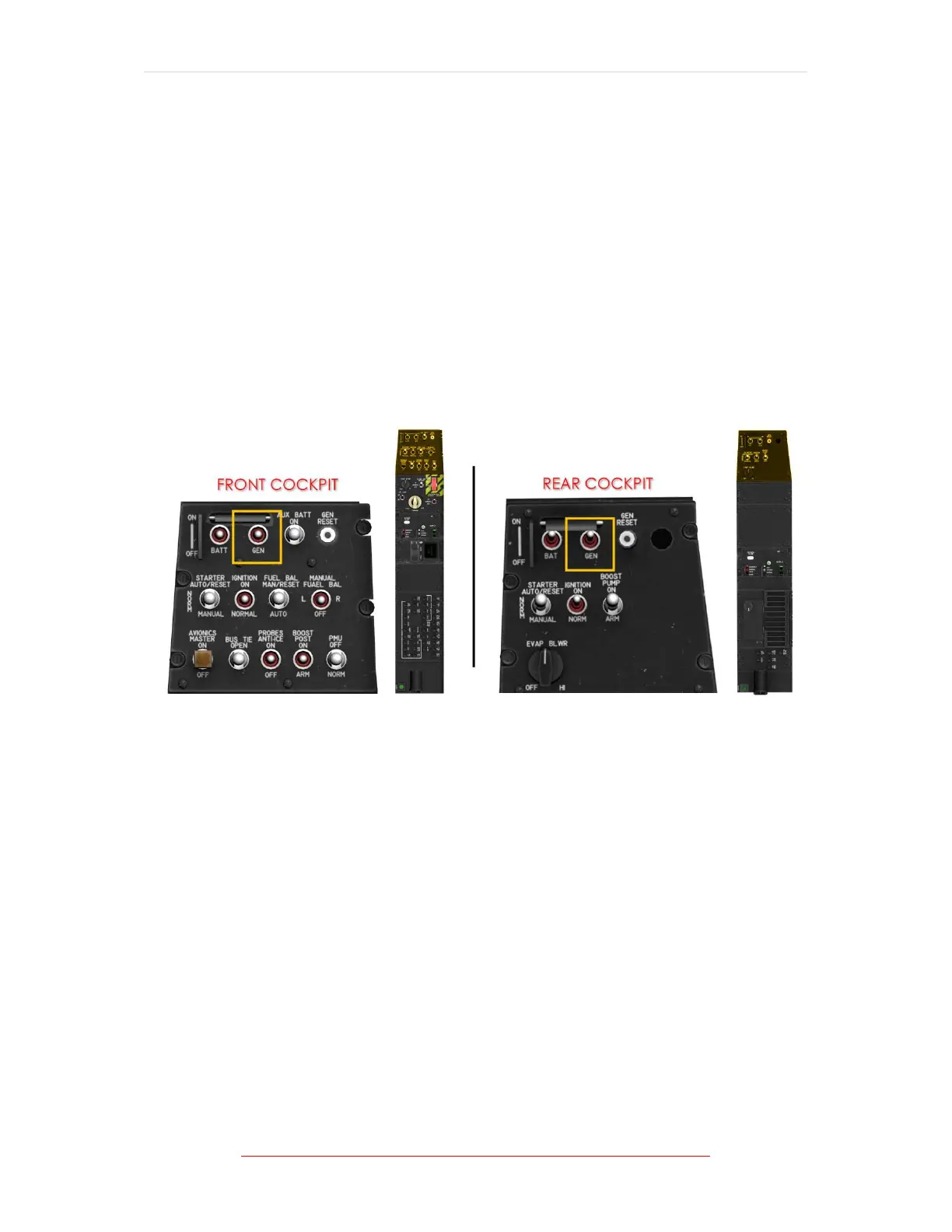
Figure 1-13 Generator Switch Location/s
Primary aircraft power is provided by the generator function of the
starter/generator. The generator provides 28 VDC power which is sufficient to
operate all equipment on the generator and battery buses, and charge the battery.
NOTE
The generator needs to supply a minimum of 25 volts to charge the battery.
The generator control switches, placarded GEN, located in each cockpit, are
magnetically held on and electrically interlocked, which allows generator control
from either cockpit. Moving the generator switch to ON in either cockpit turns
generator power on.
Moving the generator switch from the OFF position to ON will trip the switch in the
other cockpit to OFF and transfers control to the cockpit with the switch in the ON
position. While control of the switches is being transferred, power remains
uninterrupted.