I A P 2 0 2 3 . 0 0 1 - A F M / I R I S T E X A N I I P A G E | 54
FOR SIMULATION USE ONLY – NOT A TRAINING AID
WING FLAPS
The aircraft is equipped with hydraulically operated, electrically controlled, four-
segment split flaps. Normal hydraulic pressure is used for extension and retraction,
and emergency accumulator pressure is provided for emergency extension only.
The system includes two flap selectors, two selector valves for normal operation,
an emergency extension selector valve, flap actuator, flap torque tube, two flap
position indicators, and associated micro switches.
EXTENSION/RETRACTION
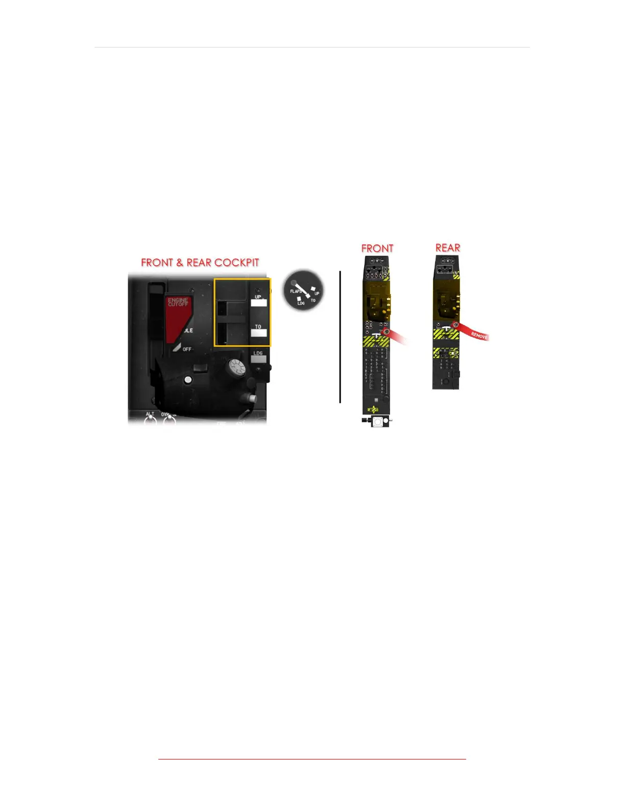
Figure 1-18 Flap Position Lever Location
The flap control system operates the flaps through a centrally located hydraulic
actuator. Flap position is controlled by a three-position flap selector, placarded UP,
TO (take-off, 23° deflection), and LDG (landing, 50° deflection), located in the left
console in each cockpit.
The selectors are interconnected so that operation of one selector is duplicated by
the other. Electrical power for the flap system is provided through a circuit breaker,
placarded FLAP CONT, located on the battery bus circuit breaker panel in the front
cockpit.
During normal operation, the flap selector controls the hydraulic flap actuator,
which is connected to the flap torque tube. When hydraulic power is applied to the
actuator, the actuator rotates the torque tube and flap segments to the selected
setting.
As the torque tube rotates, a cam on the torque tube activates position sensing
micro switches to drive the flap indicator in each cockpit.