I A P 2 0 2 3 . 0 0 1 - A F M / I R I S T E X A N I I P A G E | 49
FOR SIMULATION USE ONLY – NOT A TRAINING AID
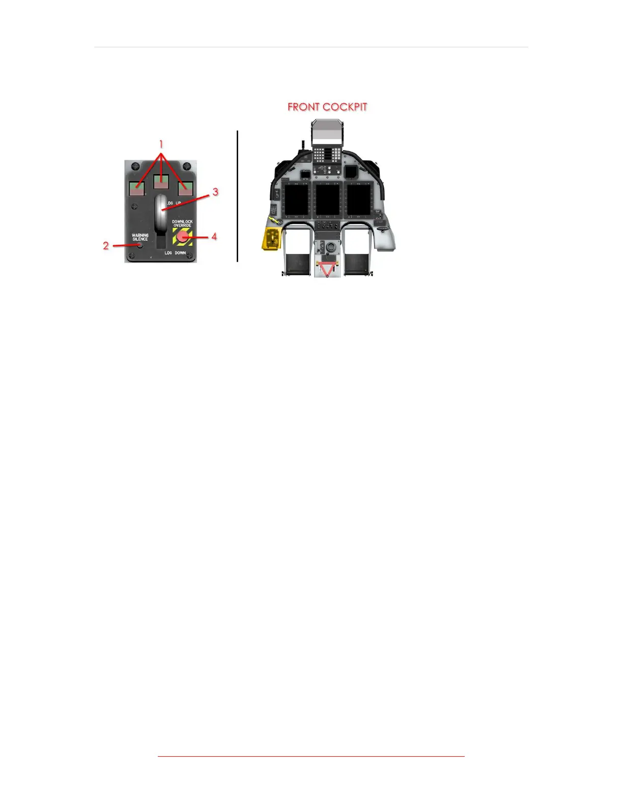
CONTROLS AND INDICATORS
1. LANDING GEAR INDICATOR LIGHTS 3. LANDING GEAR HANDLE
2. WARNING TONE SILENCE BUTTON 4. DOWNLOCK OVERRIDE BUTTON
Figure 1-17 Landing Gear Control Unit Location
The control unit, located on the lower left side of the instrument panel in each
cockpit, includes a lighted landing gear handle, landing gear position indicator
lights, a WARNING SILENCE button, and a DOWNLOCK OVERRIDE button (front
cockpit only).
Landing gear handles in each cockpit are linked mechanically, and a soft detent
prevents inadvertent control handle movement. Power for the landing gear controls
is supplied through a circuit breaker, placarded LDG GR CONT, located on the front
cockpit battery bus circuit breaker panel.
The gear indications include a red light in the gear handle and a red and green
indicator for each gear. The green indicator illuminates when that gear is down and
locked. The gear handle and red indicator illuminate whenever the nose gear is in
transit or main gear doors are not closed, or any time the PCL is approaching IDLE
with the gear handle UP, regardless of airspeed or position of main gear. The gear
handle illuminates when any red indicator is illuminated.