I A P 2 0 2 3 . 0 0 1 - A F M / I R I S T E X A N I I P A G E | 79
FOR SIMULATION USE ONLY – NOT A TRAINING AID
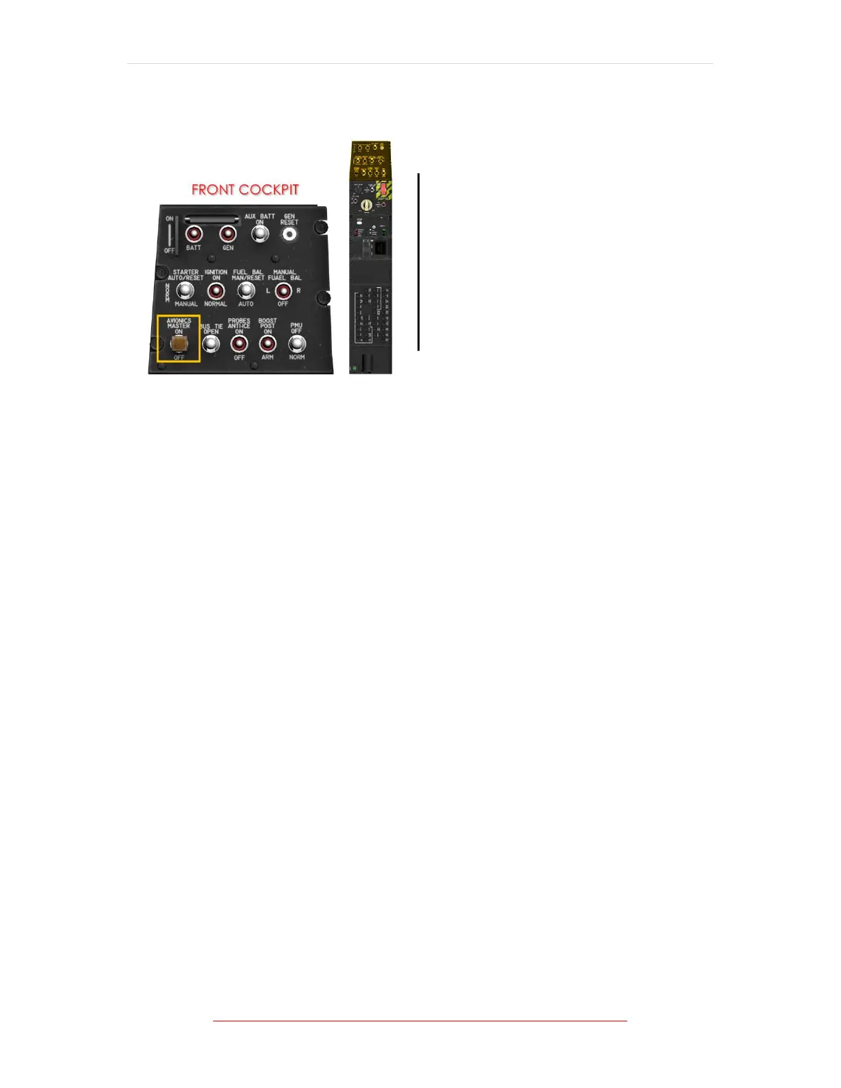
AVIONICS MASTER SWITCH
Figure 1-21 Avionics Master Switch Location
The avionics master switch is placarded AVIONICS MASTER and located on the
electrical switch panel in the front cockpit. It powers the left and centre MFDs (both
cockpits), IAC 2, UHF radio, ADC, DME, TCAS, RAD ALT, transponder, and the VHF
navigation radio.
In conjunction with the avionics systems powered by the battery, placing the
avionics master switch in the ON position enables full integrated avionics suite
operations. Navigation and primary flight information will be displayed on the left
and centre display respectively.
UFCP control of the remaining radio transceivers is enabled and both IACs are
keyed to begin synchronized operations. When the avionics master switch is placed
in the ON position, it de-energizes electrical relays allowing the forward and aft
avionics buses to be powered by the battery and generator buses.
When the AVI MSTR circuit breaker is pulled, placing the avionics master switch in
the OFF position will not turn off power to the avionics.
If the battery bus is not powered (BUS TIE switch in NORM position), the generator
bus will power the forward and aft AVI generator buses and AVI battery buses
regardless of the position of the avionics master switch.
AVIONICS BAYS
Two avionics bays, located behind the rear cockpit on each side of the aft fuselage,
house avionics equipment. The bays contain two shelves each, and each bay is
accessed through a side-hinged door.