29
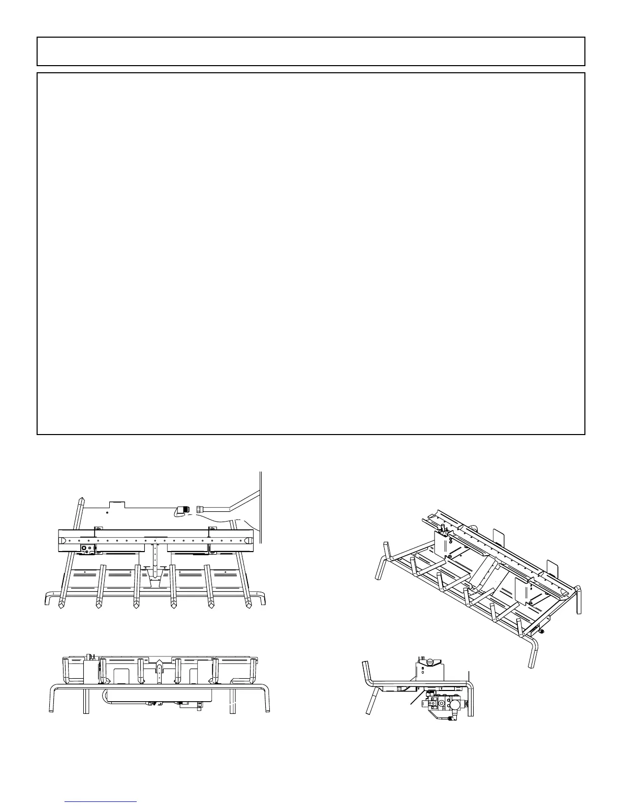
ISO-FLAMES Gas Log Burner Installation
The gas control valve is installed on the right side of the ISOFLAMES gas log burner. If the gas supply line comes into the left side
ofthereplace,thegassupplylinemustcontinuetotherightsideofthereplace(asclosetotherearreboxwallaspossible)and
terminate behind the gas valve inlet using rigid 1/2” black iron pipe. At this point only the 3/8” aluminum manifold can be used to
completetheconnectiontothegascontrolvalve.Itmaybenecessarytocutandrearethealuminummanifoldtothedesiredlength
for proper positioning of the burner pan.
Step1.Removeallashesanddebrisfromreplace.
Step2.BesuregascontrolvalvetoreplaceisintheOFFposition.
Step3.PlacetheISOFLAMESgaslogburnerinreplacewithgratespokestowardfrontofreplaceandverticalbafeshouldbein
line with chimney.
NATURAL GAS OR LIQUID PROPANE
A.Applypipethreadsealertogassupplylinecomingintoreplaceandinstall3/8”x1/2”brasssupplyttingtighten.
B.Installlongerendofaredaluminummanifoldwith3/8”brassairnutto3/8”x1/2”brasssupplyttingconnectedto
gassupplylinecomingintoreplace,andshorterendtorearofgascontrolvalvetighten.
C. When connections are complete, NEVER TEST FOR GAS LEAKS WITH A LIT MATCH OR FLAME. Slowly turn gas
control valve to the ON position and use 50/50 soap and water solution with a toothbrush or small paint brush over all gas connections.
A leak will be evident by observation of bubbles on gas connections. If bubbles are observed, retighten leaking gas connectors.
Gas Log Installation:
See pages 36 & 37. Logs are reversible for either a classic bark look, or a rugged split look.
WARNING:Failuretopositionitemsinaccordancewiththesediagramsorfailuretouseonlypartsspecicallyapprovedwiththe
ISOFLAMES gas log system may result in property damage or personal injury.
 Loading...