Firebrick
side
Gas or electric
line
NOTE: Fill any gaps around
line with Earthcore Mortar
Flex duct to fireplace
firebox (all parts non-combustible)
Exterior wall
Exterior air vent
with dress plate
Supply air ventilation
(if required by code)
ypical placement of
gas or electric line
(see detail below)
NOTE: Gas lines and combustion
air ventilation placement can be reversed.
This page used for illustration of systems
only.
16
AccessModication:
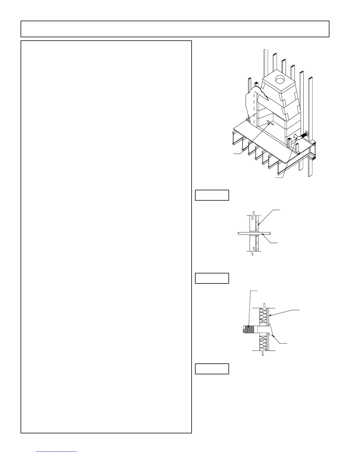
1. Gas Line Feed: These provisions for installation of a gas pipe is only
for connection to the included ISOFLAMES decorative gas log set. The
ISOFLAMES decorative gas log set incorporates an automatic shutoff
device and complies with the Standard for Decorative Gas Appliances
for Installation in Vented Fireplaces, ANSI Z21.60. The ISOFLAMES
decorative gas log set should be installed in accordance with the
ISOFLAMES Gas Log installation manual (pages 30 through 37) and
per the National Fuel Gas Code, ANSI Z223.1.
The gas line for the ISOFLAMES gas log set used in the IBV
reboxshouldberoutedthroughtheleftsidewalloftherebox(left,
when facing the unit) by drilling an appropriately sized hole using a
masonry drill bit (Figure 13).
CAUTION: Avoid the high temperature wire when drilling gas line
hole.
Notes:
1. Gas Line and Electric Line must be fed through separate access
holes.
2. Combustion Air Inlet: Combustion air inlet kits though not required
forIBVmayhelpimprovereplaceoperation.(Figure14&15).Check
local codes for combustion air requirements.
The access door is tted into the nished re brick lining at
theinterioroftheIBVrebox.Thetwelveinch(12”) long sleeve can
beintroduced into thereboxright handsidewall bycoredrilling an
appropriately sized hole through the righthand side wall keeping the
holetwoinches(2”)abovetheroughooroftherebox.(Figure13)
The hole size should allow for a one quarter inch (1/4”) mortar joint
aroundtheairaccesssleeve.Thesleevepassesthroughthereboxwall
andmustbeconnectedtometalpipeeitherexibleorrigidthatleads
to the source for outside combustion air, maximum length sixty feet
(60’). Maintain clearance of at least two inch (2”) to air kit sleeve as it
exits the outer surface of the IBV side wall.
All access holes must be grouted with mortar - after line or
conduit feed - to seal any gaps or cracks around line feed conduits (Figure
15).
WARNING: Do not use combustible duct material. Avoid installing
a combustion air inlet where the opening could be blocked by snow,
bushes or other obstacles. Air inlet must terminate a minimum of three
feet below the chimney cap level. Air inlet ducts shall not terminate in
attic spaces.
IBVAssemblyInstructions(cont.)
Figure 13
Figure 14
Figure 15
 Loading...