15
IBVAssemblyInstructions(cont.)
Step 5:Onceallthereboxwallcomponentsaresetcheckthe
topsurfaceofthereboxforlevel.
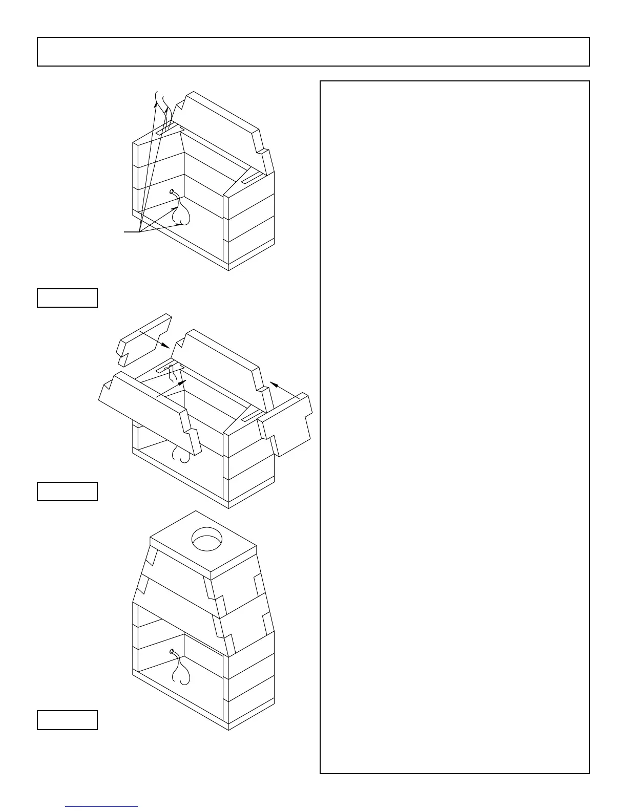
Step 6: Begin the smoke dome assembly by setting the rear
bottom smoke dome component on top of the rebox back
wall assembly in a bed of Earthcore Mortar. The smoke dome
component should sit ush with the back side of the rebox
assembly. (Figure 10)
Step7:Set the front bottom smoke dome component across the
reboxopeningsothatthesmokedomepiecespanstherebox
openingandisushwiththefrontoftherebox.
Step 8: Position the smoke dome’s sloping sidewalls at each
end of the bottom smoke dome components (Figure 11).
Theslopingsidewallstinbetweenthefrontandrear
smokedomecomponentsandalsotintothehaunchesatthe
ends of the front and rear smoke dome components.
The smoke dome sloping sidewalls have a beveled
bottomedgesothattheywillsittightontotheattopof the
reboxsidewalls.
Step 9: Set the upper course of front and rear smoke dome
components directly on top of and aligned with the bottom front
and bottom rear smoke dome components that are already in
place.
Set the two upper smoke dome sloping sidewalls into
position, one at each end of the upper front and rear smoke
dome components. (Figure 12)
Step 10: Ensure that all component contact surfaces have been
properly sealed with Earthcore Mortar.
Check smoke dome front and back walls to see that they
are plumb, level and in alignment with adjoining components.
Check alignment of the smoke dome sloping sidewall
components to see that they are ush with one another and
create smooth and uniform smoke dome Sidewalls for the total
height of the smoke dome.
Step 11: Set the smoke dome top plate into position on top of
thesmokedomewallassembly,withtheueholeclosertothe
rear. (Figure 12)
Besuretosetthesmokedometopplateushwiththe
front, back and sides of the smoke dome assembly.
High Temperature
Wire (2 pc. / 12’ long)
Figure 10
Figure 11
Figure 12
 Loading...