Drill Hole
Earthcore
Mortar
Earthcore Mortar
First Course
Back Wall
Top Course
Back Wall
Earthcore Mortar
High Temperature
Wire ( 2 pc. / 12’ long)
High Temperature
Wire (2 pc. / 12’ long)
14
IBVAssemblyInstructions(cont.)
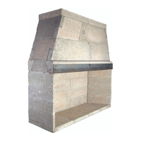
Step 2: Set therst course ofthe rebox backwall and side
walls into place on the base plate. (Figure 7)
Itmay be convenient to temporarilydry setthe rst
course of side wall and back wall into place on the IBV base
plate and then to trace their position on the base plate with a
pencil.
Remove the dry set pieces and apply Earthcore Mortar
to the areas traced on the base plate where the side walls
andbackwallaretosit.Bydoingthis,therstlayerofwall
components can be set directly into mortar already applied to
the proper areas on the base plate.
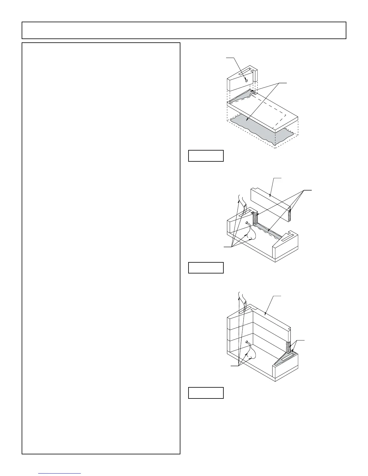
Be sure to put Earthcore Mortar on the contact
surfaces of the vertical joints where the side wall and back wall
components connect. (Figure 8)
Step 3: It is required that the two supplied high temperature
wires be routed from the inside of the IBV as follows:
Oncethelowest,lefthandsidewallreboxcomponent
issetinplace(left,whenfacingthereplace)drilla1/4”3/8”
dia. hole in the inner face of this side wall located four to six
inches (4” - 6”) out from the back wall of the IBV and at three
to four inches (3” - 4”) above the IBV base plate. (Figure 9)
This drill hole must intersect the hollow core
oftheIBVreboxsidewall.
Feed the two lengths of high temperature wire from
the inside of the IBV rebox through the drill hole and into
hollow space of the rebox side wall. Bring the two lengths
of wire up and out through the top of the side wall component
(Figure 9).
Step 4: Continue assembly of the second and third courses of
the rebox side wall and back wall.Apply Earthcore Mortar
to the top of each layer of wall components, then set the next
course above into place.
Be sure to apply mortar to all vertical joints of the side
wall to back wall connection when setting each component to
its mate. (Figure 9)
LookforsomeEarthcoreMortartosqueezeoutalong
the joints of all component contact surfaces as a sign that the
joint is thoroughly sealed with mortar.
Continue to feed the two high temperature wires up
through the hollow core of the left hand sidewall stack.
Be sure to leave approximately four feet (4’) of each of
the two high temperature wires out of the top of the left hand side
wallofthereboxforlaterconnectiontothehightemperature
limit switch and also four feet (4’) of each wire loose inside the
reboxforlaterconnectiontothepilotassembly.(Seewiring
diagram, page 29.)
Note:
1.HighTemperatureWireSpecications:Suppliedbyothers.
Figure 7
Figure 8
Figure 9
 Loading...