Inspection and Installation
1. Confirm that the power switch is in the OFF position and verify that there is
no dangerous voltage on the connection terminals.
2. Remove the output terminals cover of the DC output.
3. Loosen the screws of the output terminals and connect the red and black
test cables to the output terminals, and connect the ground terminal
correctly. Re-tighten the screws.
When maximum current that one test cable can withstand fails to meet the
rated current, use multiple pieces of red and black test cables. For example,
the maximum current is 1,200A, then 4 pieces of 360A red and black cables
are required.
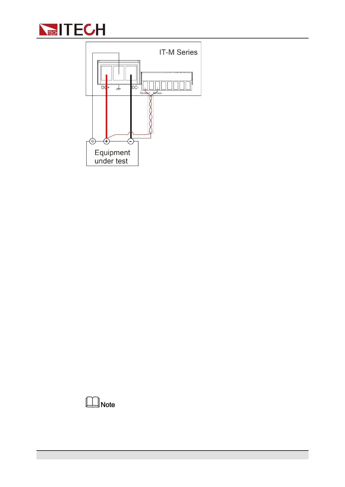
4. Refer to the wiring diagram, and use armored twisted-pair cables to connect
the remote sense terminals and the equipment under test.
5. Thread the red and black test cables and sense cables through the output
terminals cover and install the cover.
6. Connect the other end of the remote sense cables and the red and black
cables to the DUT. The positive and negative poles must be properly
connected and fastened when wiring.
7. Power on the instrument.
8. Turn the sense function on.
a. Press[Shift]+[P-Set](System) to enter into the system menu interface.
b. Rotate the knob to select Sense and press [Enter] key to make the
parameter in modification.
c. Rotate the knob to select On or Off, select On and press [Enter] to
confirm.
d. Press [Esc]key to exit.
To ensure the stability of the system, use armored twisted-pair cables
between the remote sense terminals and the equipment under test.
Copyright © Itech Electronic Co., Ltd.
23

 Loading...


