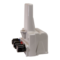
Refer to the Field Deployment Manager Tools Mobile Application Guide for programming
information.
After programming, the 500WERTModule enters the selected operating mode and begins
to bubble up specified messages at the chosen rate.
Caution!
■
The FC300SR or Itron Mobile Radio are the only devices that support programming for the 500WERTModule.
■
Keep a minimum of 12 inches between the 500WERTModule and programming device while programming
configuration changes are completed.
■
Do not place the programming device antenna directly on the 500WERTModule.
Encoder-type Register Connections
Connect the wires from the 500WERTModule to the register screw terminals according to
the following table.
Note: Itron recommends 19-26 gauge, pre-bonded or solid conductor wire with a maximum diameter of
.082 inches (individual wire insulation). The use of un-bonded wire may produce an unreliable connection
when using gel caps for joining wires.
Remote 500WERTModule wire color
Brown (data) Gray (power/clock) Yellow (ground)
Register manufacturer Register screw color designator
■
ADE
■
Badger
■
E Series
■
HR E LCD
■
HR E Mechanical
Green Red Black
Badger M5000 Mag Meter Green terminal: Out
4+
Red terminal: Input + Black Input - and Out
4 -
■
AquaMaster
■
AquaMaster III
■
Elster AMCO
■
Invision
■
Scancoder
Red Green Black
Diehl Hydrus Green White Brown
■
Elster AMCO
■
evoQ4 (Sensus Protocol)
■
Q200 (Sensus protocol)
■
SM 700 (Severn Trent)
Green Red Black
Elster AMCO evoQ4 Mag Red White Black
Gen5 500WERTModule Remote Installation Guide 2 Initializing and Connecting
December 5, 2022 LDI-0343 REV002 Itron, Inc. Page 13 of 48

 Loading...