76
Item Dimension Description
A 230 Upper fixing point (1) to lower fixing points (centre to centre)
B 201 Upper fixing point (2) to lower fixing points (centre to centre)
C 150 Left to right lower fixing points (centre to centre)
D 252 Upper fixing point (1) centre to lower edge of meter body
E 4 Lower edge of meter body to lower edge of short terminal cover
E 58 Lower edge of meter body to lower edge of standard terminal cover
E 93 Lower edge of meter body to lower edge of long terminal cover
All dimensions are in millimetres.
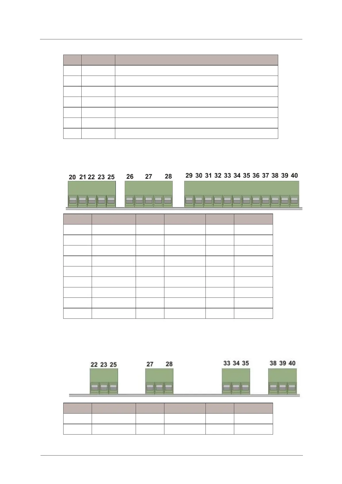
9.5. Auxiliary and communication wiring
Auxiliary wiring for Full IO Board
Terminal Function Terminal Function Terminal Function
20 Control output 1 29 Pulse output 1 36 Pulse input 1
21 Control output 2 30 Pulse output 2 37 Pulse input 2
22 Control output 3 31 Pulse output 3 38 Pulse input 3
23 Control output 4 32 Pulse output 4 39 Pulse input 4
33 Pulse output 5 40 PI Common
25 CO Common 34 Pulse output 6
26 Control input 1 35 PO Common
27 Control input 2
28 CI Common
The control output and input terminal blocks accept cables up to 2.5mm².
The pulse output and input terminal blocks accept cables up to 1.5mm².
Auxiliary wiring for Light IO Board
Terminal Function Terminal Function Terminal Function
22 Control output 1 33 Pulse output 1 38 Pulse input 1
23 Control output 2 34 Pulse output 2 39 Pulse input 2

 Loading...