Page 6
Figure 9. Vent and combustion air terminals at exterior
wall.
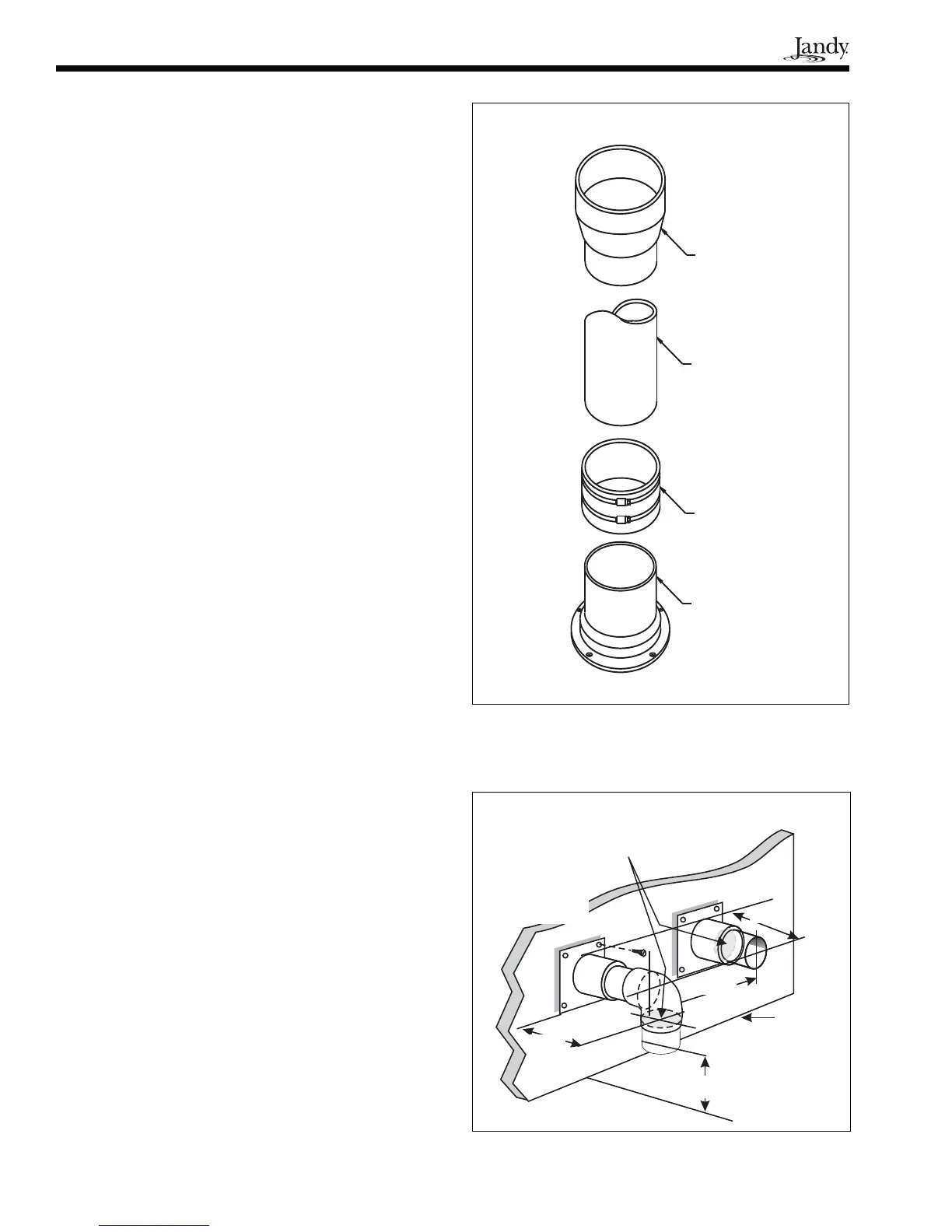
Figure 8. Indoor vent connection, Hi-E2 pool heater
2G-3d. Combustion Air and Vent Pipe
Installation
The Hi-E
2 must be vented to the outdoors.
It must not be vented in common with any other
appliance, even if that appliance is of the condensing
type. Common venting can result in severe corrosion
of the Hi-E
2 or of the other appliances or their venting,
or escape of combustion product gases through
such appliances or vents. Do not vent the Hi-E
2 to a
fi replace chimney or building chase.
Combustion air ducting, when provided, must
not be shared with any other appliance or with another
Hi-E
2. Doing so may result in fl ow of air through the
other appliances instead of directly from the outdoors.
The combustion air intake and vent outlet must
be located exterior to the building and in the same
pressure zone - i.e. both through the roof or both
through a side wall. The vent terminal must be located
in accordance with local codes, as applicable, and in
accordance with the following:
1. Locate the vent terminal so that it will not be
damaged by pedestrians and other traffi c, and so
that the discharge is not offensive. The National
Fuel Gas Code requires a through-wall vent
terminal be at least 7 feet (2.13 m) above grade if
located at a public walkway.
2. Locate the vent terminal so the vent exhaust does
not settle on building surfaces and other nearby
objects. Vent products may corrode such surfaces
or objects.
3. Locate the vent terminal at a suffi cient horizontal
distance from any gas or electric metering,
regulating or relief equipment. In the United
States, this distance must be at least 4 feet
(1.21m). In Canada, it must be at least 10 feet
(3.04m).
4. Locate the vent terminal at a suffi cient horizontal
distance from any building opening. Take special
care to assure that combustion products do
not enter a building through windows, doors,
ventilation inlets, etc. In the United States, this
distance must be at least 4 feet (1.21 m). In
Canada, it must be at least 10 feet (3.04 m).
As shown in Figures 9 and 10, the combustion air
intake and the vent outlet must be installed no closer
together than 18" (45.7cm) and no farther apart than
60" (1.5m). The combustion air inlet opening must
face downward to prevent entry of rain or snow. The
vent outlet must discharge away from the combustion
air inlet - normally in a horizontal direction when on
a wall and vertically upward when on a roof. Both
should terminate at least 12" (30.5cm) above the snow
accumulation level. In locations with freezing climate,
extension of the vent pipe outside of the building
7" min.
12" min.to
maximum snow level
Grade level
or normal
snow
18" min.
60" max
6" min.
Vent Exhaust
Pipe
Special insect screens installed
(see Figure 11)
Combustion
Air Pipe
PVC Adapter
when required
4" PVC Pipe
Field-provided
Clamping Con-
nector
with Neoprene,
Nitrile or EPDM
Sleeve
Hi-E2 Vent Collar