Model LJ Pool and Spa Heater
Page 39
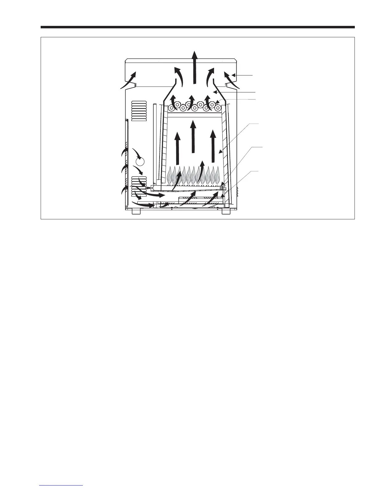
open end of a burner. When the gas flows into the
burner, a “negative” pressure is created at the opening
of the burner. This negative pressure pulls air into the
burner with the gas and mixes the two together. As
the gas/air mixture flow through the burner ports it is
ignited in the combustion chamber. Hot combustion
products then raise through a highly efficient heat
exchanger. Combustion products then enter a flue
collector and are directed to the outdoors through the
grate top of the heater or a vent pipe and cap.
10.3 Heater Components and Their
Operation
1. Gas valve / Regulator - The gas valve controls
gas flow into the manifold. It provides flow only
when the temperature controls require heat and
only if all safety controls enable operation. It is
also a positive pressure regulator. It regulates
the gas pressure in the manifold to specifications
addressed earlier in this manual. This is neces-
sary for proper operation of the burner system.
2. LJ Temperature Control/Ignition Control
Combination System-
a. Temperature Control-The Jandy LJ
controller is an electronic control which senses
water temperature by means of a thermistor and
controls heater operation to bring the water to the
temperature selected. It has an option for two
separate thermostat settings which are typically
used to set pool and spa temperatures. A push-
button selector key is used to switch between
settings.
b. Ignition Control - The ignition control is
integrated with the temperature control. It
provides energy for ignition of the air/gas mix-
ture, monitors the flame and controls the gas
valve. When the temperature control requires
heat, the ignition control provides a pre-purge of
the combustion chamber. Then it applies electri-
cal power to a “hot surface” igniter. When the
igniter is hot enough, the ignition control opens
the gas valve. It has sophisticated means to
sense ignition and flame condition so that un-
burned gas will not escape. After the burner is
shut off, the ignition control continues operation
to provide a post-purge period.
3. Igniter - The hot surface igniter is a ceramic
composite element which becomes very hot
when electrical power is applied to it. The hot
surface igniter directly ignites the air/gas mixture
in the combustion chamber.
4. Flame Sensor - The flame sensor is the elec-
trode through which the ignition control detects
“rectification” of current passed through the
flame. Inadequate rectification indicates an
unsatisfactory flame condition. The ignition
control responds to the flame signal provided by
the flame sensor.
FLUE COLLECTOR
HEAT EXCHANGER
COMBUSTION CHAMBER
BURNER
BURNER TRAY SHELF
VENT TOP
EXHAUST
AIR
FLOW
Figure 26. Atmospheric Combustion System