Page 28
wired to the Fireman Switch connection. The LJ
controller must first be set up to recognize the remote
mode. The set up consists of setting the 'PROGRAM'
(pump time clock) 'ON' and 'OFF' times to run for 24
hours, setting the controller function to 'SPA' and
setting the spa temperature to 104°F (40°C).
To set the LJ controller for remote control use,
follow the instructions at the beginning of this section
setting the controller into the "External Time Clock"
mode.
To operate the heater by the remote unit, use the
SELECT key on the LJ controller keyboard to set
the heater to the 'SPA' mode.
Then follow the instructions in Section 7.2.3,
"Setting the Pool and Spa Temperatures", to set the
spa temperature limit to 104°F (40°C). This will allow
the remote system's temperature settings to control the
water temperature to a maximum of 104°F (40°C).
The LJ controller now acts as a "slave" controller
and heater functions are controlled by the remote
control system.
To restore control of the heater functions to the
LJ controller, disconnect the remote system from the
Fireman Switch, reprogram the pump time clock to
desired settings and reset the 'SPA' temperature to the
desired setting.
7.5.2 Remote Control Connected At The
Heater's Control Panel
The LJ heater control also provides the option of
using a remote switch to change the mode of the
heater. This remote will allow the user to change the
mode of the heater between 'POOL', 'SPA' and 'OFF'.
A more functional remote may be installed as stated in
the previous section.
A special Jandy wire harness is needed to install
the owner provided remote mode switch. Contact your
local Jandy distributor to order the wire harness kit
(Part Number R0398400). The wire harness kit
includes detailed instructions for the installation of the
wire harness and remote switch.
7.6 Water Pressure Switch Adjustment
CAUTION
The water pressure switch should be adjusted
to turn the heater off when the pump is off.
Setting the switch to close at too low of a flow
can damage the appliance. Adjust the switch to
turn the heater off, not on.
ATTENTION
Le manocontact de pression d’eau doit être
réglé de façon à ce que l’appareil cesse de
fonctionner si la pompe s’arrête. Si le
manocontact est réglé pour se fermer lorsque
le débit d’eau est trop faible, l’appareil risque de
s’endommager. Réglez le manocontact pour
qu’il arrête l’appareil, et non pour qu’il le mette
en marche.
The pressure switch is preset at the factory for
activation at 2 psi (14 kPa). Adjust the pressure switch
only if any part of the filter system piping is 3 feet
(0.91 m) or more above the top of the heater jacket.
Do not adjust the pressure switch if the heater is
installed more than 15 feet (4.57 m) above or 6 feet
(1.83 m) below the pool surface. Consult your local
Jandy representative for recommendations.
On some installations, the piping from the heater
to the pool is very short. The back pressure could be
too low to trigger the pressure switch. If this happens,
it may be necessary to install a directional fitting or
elbows where the return line enters the pool. This will
increase back pressure enough for the heater to
operate properly.
Make sure the pool filter is clean before making
any pressure switch adjustment: A dirty filter will
restrict the water flow and the pressure switch cannot
be adjusted properly. To adjust the pressure switch:
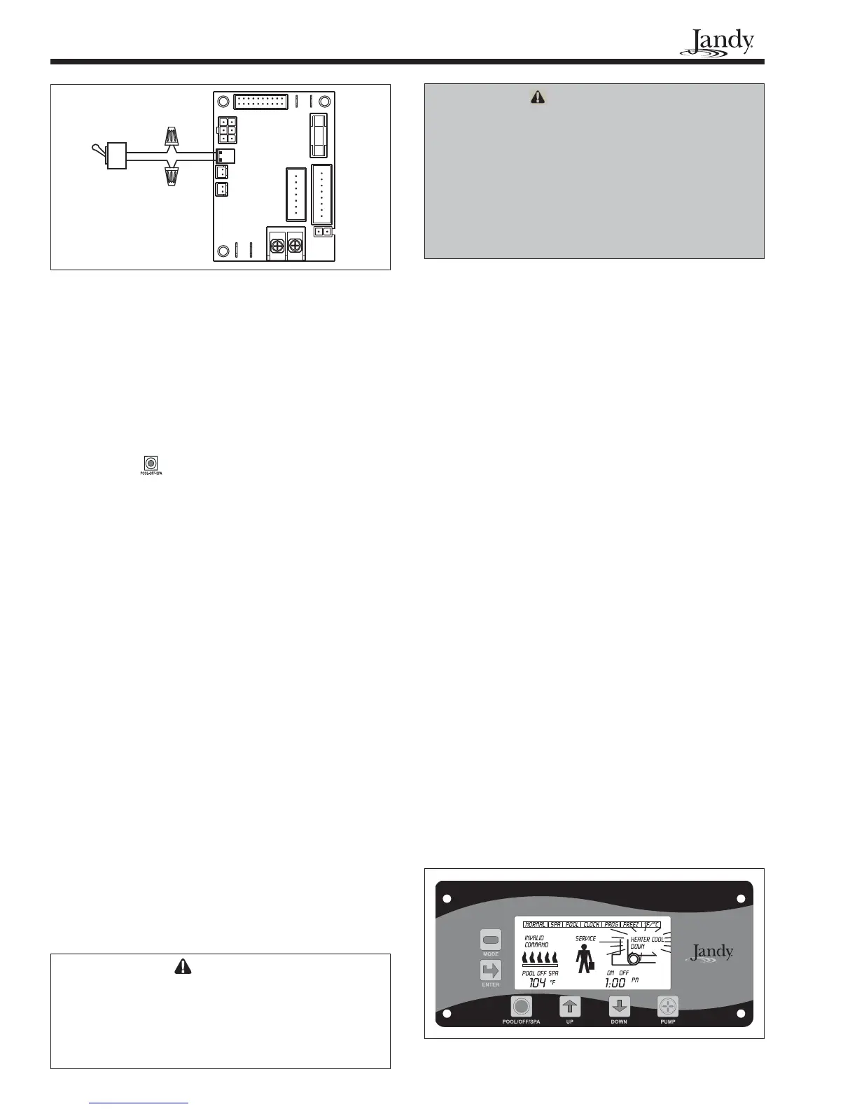
1. Turn the pump 'OFF' by pressing the PUMP key
so that the display shows that the pump is 'OFF'.
If the heater was running it should go off immedi-
ately and the pump will run in the 'COOL
DOWN' mode for 5 minutes. If the heater has
been running within the last 5 minutes, the pump
will continue to run for the remainder of the 5
minute cool down period (see Figure 20).
2. Set the pool temperature control to the maximum
setting. Repeatedly depress the MODE key until
the indicator at the top of the display shows
'POOL SET'. Press the ENTER key. Then use
the UP key to set the temperature to 104°F
(40°C). Press the ENTER key again.
CONTROLLER
FLAME SENSOR
GAS VALVE
SAFETY CIRCUIT
FIREMAN
SWITCH
PUMP
BLOWER
POWER IN
SELECT
PLUG
IGNITER
POWER
IN
R
POWER
IN
ON
OFF
R
Figure 19. ON/OFF Type remote switch
Figure 20. LJ controller display