LXi
™
Pool/Spa Heater Installation and Operation Manual Page 45
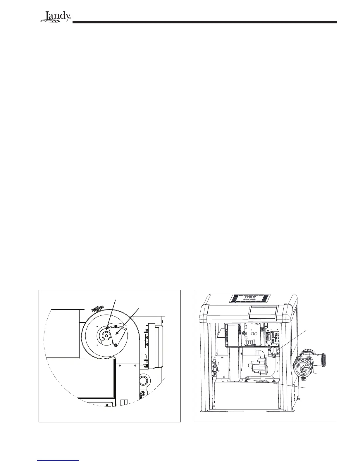
10.4.3 Burner Throat Pressure
Adjustment
The burner throat pressure should be adjusted
using the air orifi ce on the intake of the fan. This air
orifi ce has a slider attached to it. (See Figure 35.) This
slider is used to increase or decrease air pressure. The
air pressure will drop as more of the slider covers the
air orifi ce. The air pressure will increase as more of the
air orifi ce is exposed. The pressure should be adjusted
to 1.0" W.C. To measure the air pressure locate the
burner throat pressure tap. (See Figure 36). Remove
the plug covering the tap and measure the pressure.
10.5 Electrical Troubleshooting
This section describes procedures for checking
the electrical power and control components of the
heater one at a time and in the order they appear in the
control circuit. It is important to follow the sequence
of this troubleshooting guide because the safety circuit
is connected in series.
These procedures require a Volt-Ohm meter
with a minimum 0-250VAC voltage range, and
1-1000 Ohm resistance range. Figure 37 shows
the power and control circuits and where to take
measurements. Location numbers in circles have
been added, and will be referenced in the following
sections.
Where test points are shown at circuit board con-
nectors, the probe of the meter can be carefully pushed
into the connector along side of the wire at the connec-
tion to be measured.
The electrical power supply can be checked with
the heater not set to fi re. All other procedures need to
be checked with power correctly supplied to the heater,
all external devices set so that the heater is allowed to
fi re and the heater's thermostat set so that there is a call
for heat.
As stated at the beginning of the manual, some
of these procedures are hazardous. Only a qualifi ed
service technician should service the heater.
10.5.1 Electrical Power Supply
The electrical components of the LXi pool heat-
ers are designed to operate with supply voltage ranging
from 102V to 132V at 60 Hz if connected to a nominal
120 Volt power supply, or 204V to 264V at 60 Hz if
connected to a nominal 240 Volt power supply. Mea-
sure supply voltage at the power supply leads where
they enter the heater (identifi ed as points A, B and C
on the wiring diagram in Figure 37). Use the voltages
in Table 12 to verify that the correct voltage is sup-
plied to the heater.
If no voltage is present, correct this external
power supply problem to the heater. Circuit break-
ers, time clock settings or similar devices may be the
problem. Voltage outside of the above ranges may be
due to poor wiring, poor connections, other loads such
as air conditioning compressors or to an electric utility
company problem. Arrange for correction of the volt-
age as appropriate.
When you are sure that the voltage supplied to
the heater is correct, check the voltage being supplied
to the transformer by the power supply circuit board.
Figure 35. Adjustable Air Orifi ce Location
Air Pressure
Switch
Burner Throat
Pressure Tap
Figure 36. Air Pressure Switch and Burner Throat
Pressure Tap Location
Adjustable
Air Orifi ce
Side View - Upper Left
Slider