Page 28 LXi
™
Pool/Spa Heater Installation and Operation Manual
NOTE If you install a time clock to control the fi lter
pump operation, it is recommended that
the time clock have its own low voltage
(Fireman’s) switch to turn off the heater before
turning off the pump. The switch should shut
off the heater about 15 minutes before the
fi lter pump shuts off. This will allow for a more
effi cient operation by removing any residual
heat contained in the heat exchanger back to
the pool.
CAUTION
To avoid damage to the heater, do not connect the
power supply of the heater to the output side
of the clock if your time clock simply interrupts
the high voltage power supply or has a high volt-
age output. Doing so will prevent the blower from
purging the residual heat from the heater when the
heater turns off. The blower must be allowed to run
for 45 seconds after the heater shuts off.
6.5.2.2 Confi gure the Control Panel
1. Make sure the control is in the OFF mode.
2. To enter the Service Setup mode, press and hold
the MENU, POOL, and SPA buttons for 5
seconds.
NOTE The display will revert back to OFF after one
minute since the last key press.
3. Press the Up or Down button to display RE-
MOTE. The SELECT REMOTE OFF (default
remote) appears. Use the Up or Down button to
scroll through the Remote options. When you
reach REMOTE TSTAT, press the MENU but-
ton to select the remote. Press POOL or SPA to
exit the Service Setup mode.
4. Press SPA. Adjust the setpoint to the maximum
setting of 104 °F.
6.5.2.3 Remote Operation
The LXi pool/spa heater controls can be wired
for remote operation. All Jandy AquaLink
®
RS Con-
trol Systems will permit the heater to be operated by
remote control.
If you are setting up a new pool or spa system,
call your local Jandy distributor or the Jandy Customer
Service Department, 1.707.776.8200, extension 245,
for information on the correct RS Control System to
meet your needs.
To provide “smart” communication between the
LXi and an AquaLink
®
RS PCB Board through a red
four-pin RS485 connector, your PCB firmware must
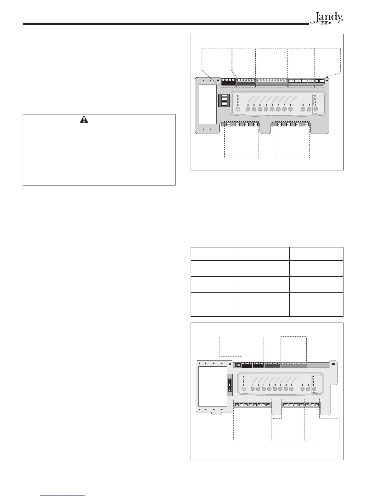
be Rev N or higher, as shown in Figure 28. To deter-
mine the REV of the PCB firmware in your systerm,
refer to Table 7 and Figures 27 and 28.
If your PCB firmware is REV MMM or lower, as
shown in Figure 27, connect the heater to the control
as indicated in Section 6.5.2.
If your PCB firmware is REV N or higher, as
shown in Figure 28, continue to follow the procedures
in this section.
Table 7. PCB Boards with Firmware REV MMM & REV N
Components REV MMM REV N
RS485
Connectors
One set of 4 Two sets of 4
JVA Sockets
24 VAC
Located on top of
board
Located on bottom
of board
Relay Sockets
24 VDC
10 total sockets. 8
located on bottom,
2 on top of board
11 total sockets.
All located on
bottom of board.
S1
S2
654321
10987654321
4321
4321
RESET
SERVICE
TIME OUT
FILTER PUM
P
AUX
1
AUX 2
AUX 3
AUX 4
AUX
5
AUX 6
AUX 7
RS6 & RS8 ONLY
RS8 ONLY
HEATER
SOLAR
POOL MODE
SPA MODE
SPA DRAIN
SPA FILL
AUTO
Connection to
Controller:
RS485 Connectors
Spa
Side
Switch
Sensors
and
Heater
Relay Sockets
24 VDC
Relay Sockets
24 VDC
JVA Sockets
24 VAC
Filter Pump
Aux 1
Aux 3
Aux 2
Aux 4
Aux 5
Aux 6
Aux 7
Intake
Return
Cleaner
Solar
Solar Pump
Elect. Htr.
Spare
Figure 27. PCB Board with Firmware REV MMM or Lower
Spa Side
Switch
Sensors and
Heater
JVA Sockets
24 VAC
Relay Sockets
24 VDC
Connection to
Controller:
RS485
Connectors
Relay Sockets
24 VDC
Relay Sockets
24 VDC
Intake
Return
Cleaner
Solar
Solar Pump
Elect Htr
Filter Pump
Aux 1
Aux 2
Aux 3
Aux 4
Aux 5
Aux 6
Aux 7
4321
654321
10987654321
RESET
SERVICE
TIME OUT
FILTER PUMP
AUX 1
AUX
2
AUX
3
A
UX 4
AUX 5
AUX 6
AUX
7
RS6 & RS8 ONLY
RS8 ONLY
HEATER
SOLAR
POOL MODE
SPA MODE
SPA DRAIN
SPA FILL
AUTO
Figure 28. PCB Board with Firmware REV N or Higher