LXi
™
Pool/Spa Heater Installation and Operation Manual Page 29
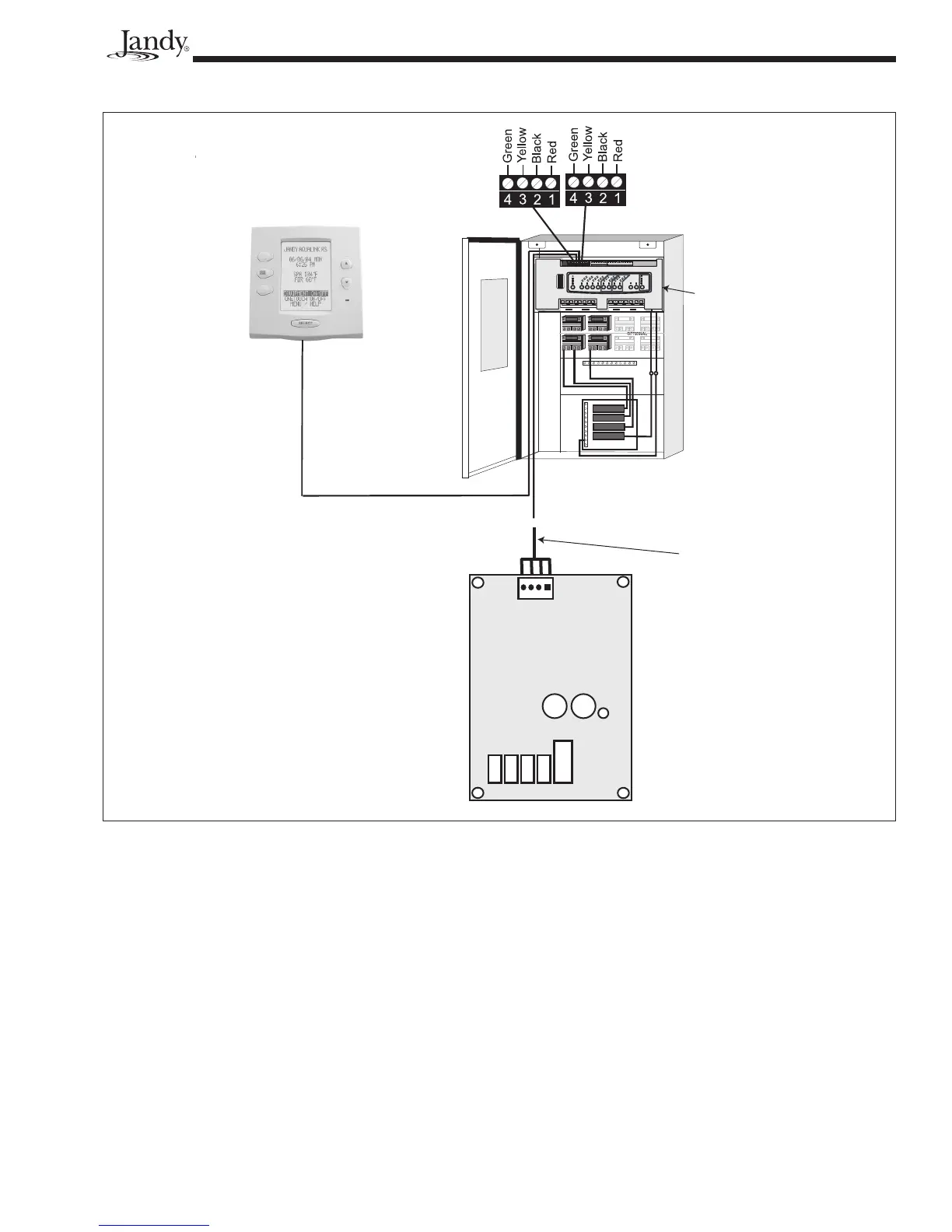
Figure 29. Wiring an LXi to a Jandy RS Remote
RESET
SERVICE
TIME OUT
FIL
TER PUMP
A
UX
1
A
UX
2
A
UX
3
A
UX
4
A
UX
5
A
UX
6
A
UX
7
RS6 & RS8 ONLY
RS8 ONLY
HEATER
SOLAR
POOL MODE
SPA MODE
SPA DRAIN
SPA FILL
AUTO
654321
10 9 8 7 6 5 4 3 2 1
4321
4321
To Sensors, etc.
(green terminal bar)
To Remote
(brown terminal bar)
To Controller
(red terminal bar)
GR Y BK R
4 3 2 1
Power Center
Indoor Controller
LXi Control
RS Control
System
Power
Center
Bezel
22 Gauge
4 Conductor
Wire
Do not connect more than two wires to any of the
terminals in the RS Control System when connecting
peripheral devices. If connecting the LXi heater to the
RS Control System creates this situation, then a Multi-
plexing PCB kit must be used. Call your distributor or
Jandy Pool Products, Inc., to order the kit.
To connect the LXi to your RS control system,
refer to Figure 29 and follow the steps listed below.
1. Turn off the power to both the heater and the RS
control.
2 Open the RS Power Center enclosure and remove
the front dead panel.
NOTE Only an RS System with fi rmware revision "N",
or higher, will support the LXi heater interface.
Refer to Table 7 and Figures 27 and 28 to
determine the REV of your system's fi rmware.
If it is "N" or higher, continue with these
procedures. If it is MMM or lower, follow the
procedures in Section 6.5.2.
3. Use 22 gauge 4-conductor wire (Jandy
part # 4278) to run between the heater and the
RS control, and match the wire color order.
4. The wires coming from the LXi heater can be
“doubled up” on the red terminal bar with the
four wires coming from the indoor controller.