Page 11
ENGLISH
Jandy
®
VS FloPro™ Variable-Speed Pumps
|
Installation & Operation Manual
VS FloPro Controller Options
The VS FloPro pump can be operated by one (1) of ve
(5) controllers: the JEP-R variable-speed controller,
iQPUMP01 controller, the AquaLink RS controller (Rev
O or later), the AquaLink PDA (Rev 4.0 or later), or
the AquaLink Z4. The VS FloPro variable-speed pump
communicates with the controllers via a four-wire
RS-485 interface.
Controller Installation Options
The VSFHP085JEP and VSFHP165JEP pumps
come pre-congured for the JEP-R variable-speed
controller with DIP switch settings pre-congured to
work with this controller. The VSFHP085AUT and
VSFHP165AUT Pumps come pre-congured for
installation with the AquaLink RS, AquaLink PDA, or
AquaLink Z4.
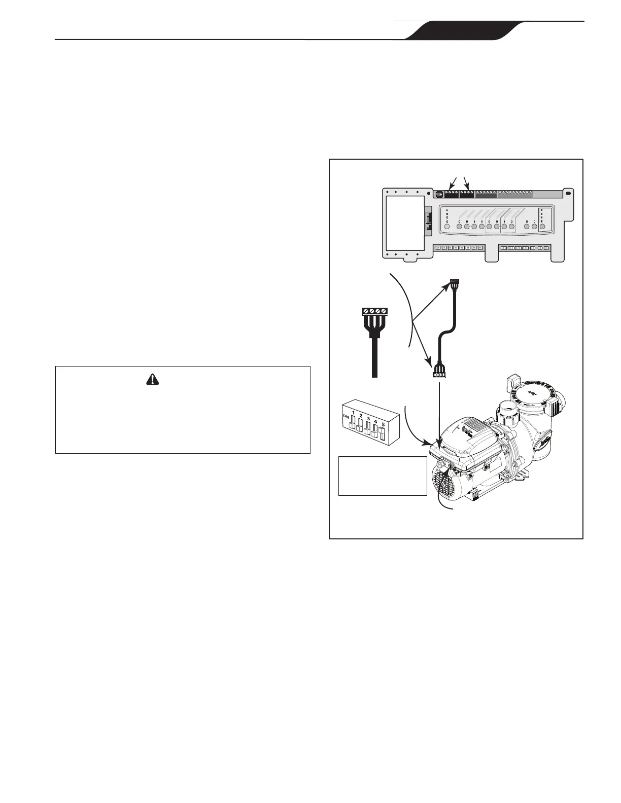
To install with an AquaLink RS controller (Rev O
or later), an AquaLink PDA (Rev 4.0 or later), or an
AquaLink Z4:
1. Remove power from the VS FloPro pump by
disconnecting the high voltage lines or by turning
off any breaker to which the VS FloPro pump
power is connected.
WARNING
ELECTRICAL SHOCK HAZARD
Turn off all switches and the main breaker in the variable-
speed pump electrical circuit, and allow five (5) minutes,
before starting the procedure. Failure to comply may cause
a shock hazard resulting in severe personal injury or death.
2. Remove the access cover to complete electrical
connections to the motor.
3. Slide DIP switches 1 and 2 down to the OFF
position. Slide DIP switch 5 up to the ON position.
See Figure 7.
4. Select the desired address(es) for the
pump by
setting DIP switches 3 and/or 4, as shown in Section
3.3, VS FloPro Pump DIP Switch Settings.
5. If short RS-485 cable or JEP-R controller is pre
installed:
a. Disconnect the RS-485 cable from the 4-pin
header on the pump drive.
Note: Do not cut the cable, or you will lose the ability to return
to the default factory configuration.
b. Connect the new RS-485 cable from the
AquaLink through the available compression
tting and route the 4-conductor cable through
the motor drive threaded port closest to the
connector. Figure 7.
6. Connect the RS-485 connector on the
AquaLink
®
RS (or multiplexer interface board),
matching wire colors with connector positions as
follows: 1-red, 2-black, 3-yellow, and 4-green. See
Figure 7.
7. Secure wiring access cover to the pump motor.
8. Restore power to the pump and verify the operation
of the controller.
9. Refer to the appropriate manual for set up and
operation of the pump: AquaLink RS Owner’s
Manual, 6593, AquaLink PDA Owner’s Manual,
H0572300, or AquaLink Z4™ Owner’s Manual,
H0386600.
Variable-Speed
Pump
4321
RED
BLACK
YELLOW
GREEN
RS485
Cable (22 AWG)
BLACK
YELLOW
RED
GREEN
Connect to
AquaLink RS
RS-485 Connector
(or Multiplexer
Interface Board)
S1
S2
RESET
SERVICE
TIME OUT
FILTER PUMP
AUX 1
AUX 2
AUX 3
AUX 4
AUX 5
AUX 6
AUX 7
RS6 & RS8 ONLY
RS8 ONLY
HEATER
SOLAR
POOL MODE
SPA MODE
SPA DRAIN
SPA FILL
AUTO
654321
10 9876 54321
4321
4321
AquaLink
®
RS RS-485 Connectors
5-Position
DIP Switch
Power Wiring Port
200 ft (61 m)
max install distance
for communication
Product may differ from images shown
Figure 7. Wiring AquaLink RS Controller or
AquaLink PDA
 Loading...