Page 27
These specifications presuppose a yearly calibration and a warm up time of 10 minutes.
Used abbreviations:
rng = of measuring range
rdg = of measured value
1)
Measuring range with scale factor = 1, (Current tranformer = 5/5A, 1/1A)
2
) In the range of -10..18°C and 28..55°C, an additional error of +-0,5‰ of measured value has to
be considered per K.
3
) If the measured apparent power is in the range of 1% .. 100% of the measuring range, cos(phi)
is indicated with an accuracy of +-3%.
4)
Accuracy class according to DIN EN61036:2001-01, VDE0418part 7, IEC61036:1996 + A1:2000
5)
The auxiliary voltage is taken from the measuring voltage.
6)
The maximum indication range and the resolution of real and reactive energy depends on
Transformer ratio v = vi * vu.
vi = Transformer ratio of current transformer.
vu = Transformer ratio of voltage transformer.
Example: 200/5A -> vi = 40
1000/100V -> vu = 10
v = vi * vu
v = 40 *10
v = 400
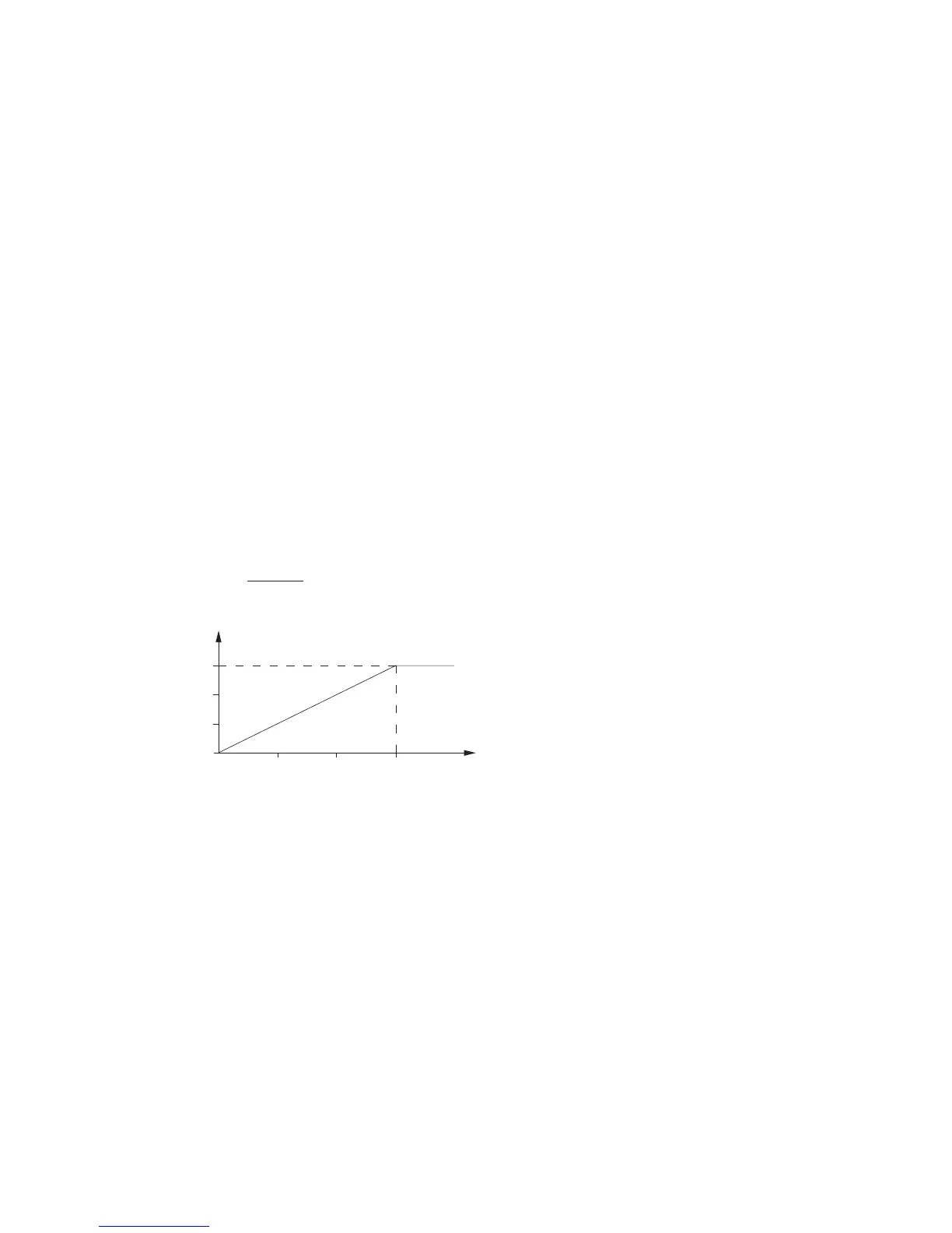
1 10 100 400 v
999.999.999
210.000.000
21.000.000,0
2.100.000,00
Energy
/kvarh /kWh
Transformer ratio v
Indication range and resolution for
real and reactive energy
 Loading...