janome.com
Page 9
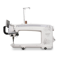
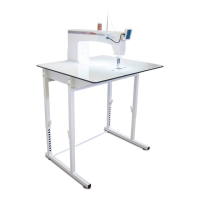
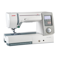
1. Place the carriage, wheels down, on the table rails,
ensuring that the Carriage Encoder Assembly (small
black box) is positioned on the opposite side from the
frame poles. Be sure to place the carriage on the frame
correctly (see Figure 3).
2. Place the machine on the carriage with the back of
the machine on the same end as the Carriage Encoder
Assembly. Be sure that the silver rails on the carriage
are inserted into the groove in the machine wheels.
3. On the rear of the machine there is a ribbon cable
attached and folded up. Unfold the ribbon cable and
plug the unattached end of the ribbon cable from the
machine into the Carriage Encoder Assembly. The
connector is keyed to assure correct alignment. Make
sure the keyed portion of the cable connector aligns
with the keyed portion of the encoder connector. Do
not force.
5. REMEMBER that if the machine is to be removed
from the carriage, the cable must be disconnected
from the Carriage Encoder Assembly. The other
two connectors on the cable should remain in place.
Failure to unplug the cable when removing the
machine from the carriage could result in damage to
the cable, encoders, and carriage.
Installation (Quilt Maker Frame)
Figure 3
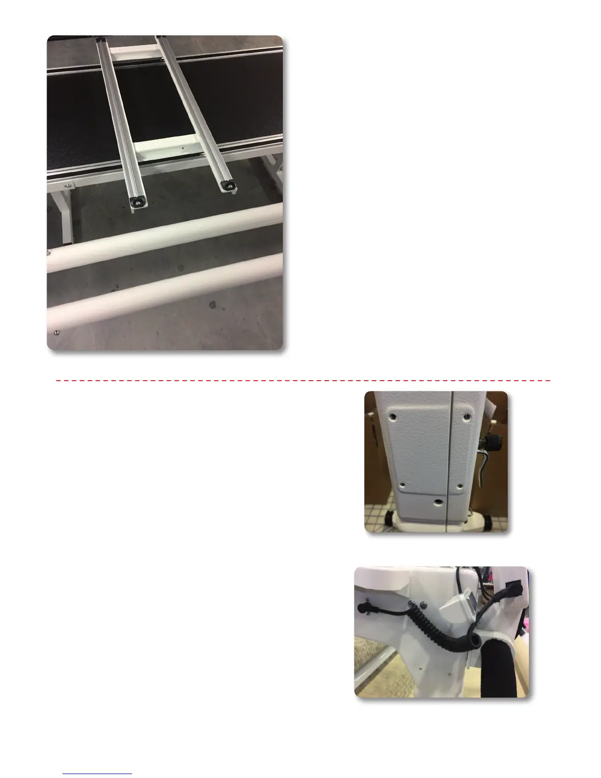
Installing Front Handlebars
Caution: Unplug the Janome Quilt Maker Pro 18 from
the electrical outlet. All power to the machine must be
turned off when installing the front handles. Failure to do
so can result in damage to the machine.
Locate the handlebar with lights and magnets attached—
this is the front handlebar. On the front of the machine
locate the 4 threaded holes in a square pattern. (See
Figure 4) Use the 4 bolts found in the machine accessory
box in the small bag with the black spiral serial cables
to attach the front handlebar mounting plate using the
included 4mm hex wrench.
Find the serial connection point on the left side of the
front display and the serial connection point on the
left side of the front of the machine. Connect the front
display to the machine using one of the black spiral serial
cords. (See Figure 4.1) Be careful to align the pins in the
cord with the pins in the serial connection points. Insert
carefully.
Handlebars can rotate to desired position by loosening
the bolts and rotating the handlebars being sure to not
pull them out.
Note: There are magnets on the reverse of the lighting
for convenient storage.
Figure 4
Figure 4.1