A WILKINSON STAR LIMITED PRODUCT 01-19 ISSUE 1
Tungsten chart
Gas purge
Press the panel and the gas will ow
through the machine and torch. In
addion “GAS” will be lit in the display.
Press again and gas will cease to ow and
the indicator in the display will go o. If the buon
is not pressed to exit the gas purge condion it will
exit automacally aer 30 seconds.
TIG parameter sengs
To adjust a parameter rotate the adjuster knob to
the selected parameter LED. Press the adjuster knob
and the LED will ash. Make the
adjustment and press the
adjustment knob and the LED will
cease ashing conrming the
parameter is saved.
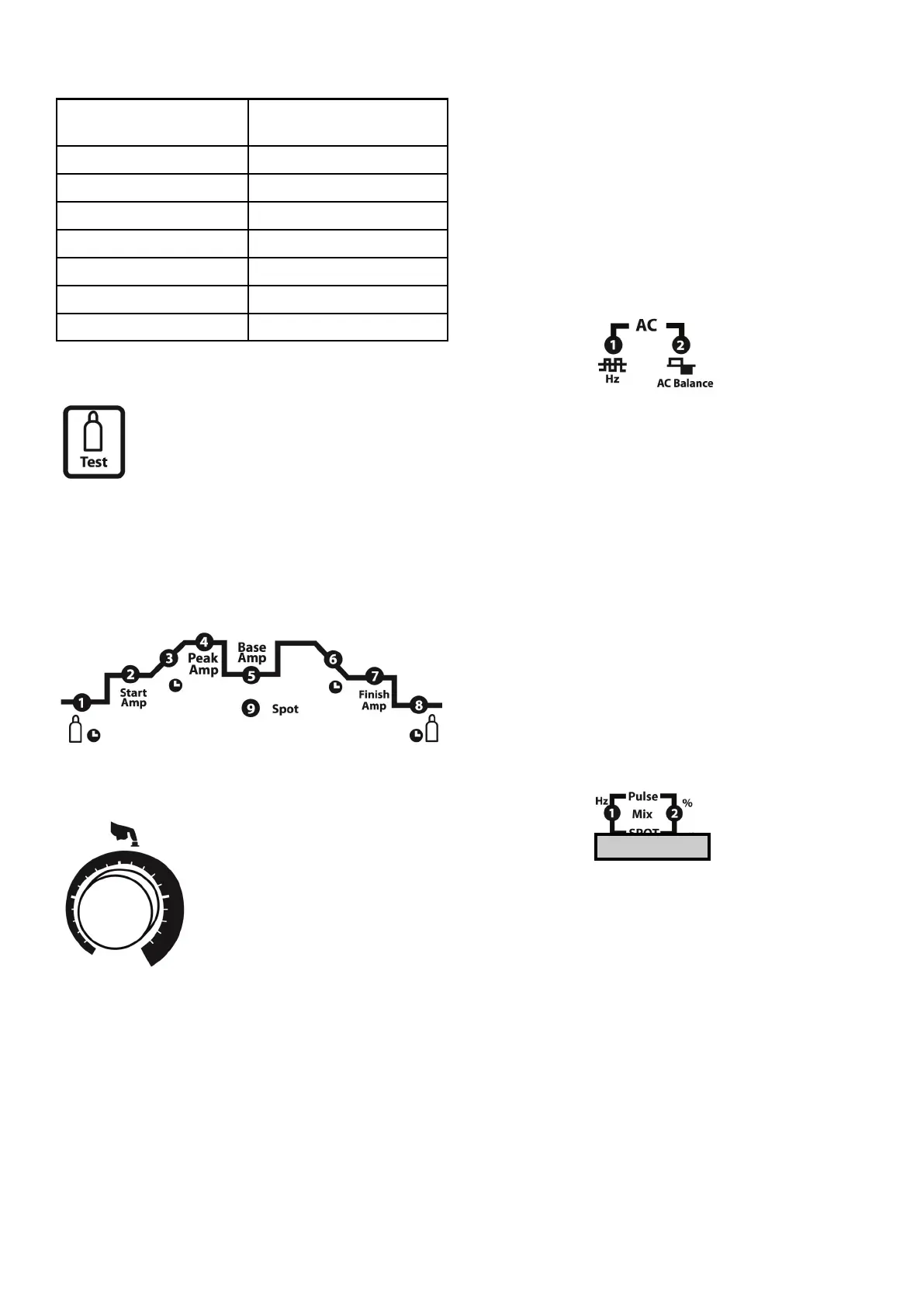
1 Preow gas me (secs). This
is the me gas will ow before
the arc starts.
2 Start amperage seng (amps).
3 Upslope me (secs). Time the current takes to
go from the start amperage to set welding
current.
4 Peak amps (amps). This is normally the
selected welding current maximum.
5 Base amps (amps). This is the background
current when pulse welding mode is used.
Cannot be selected unless pulse mode is
enabled.
6 Downslope me (secs). Time the current takes
to go from the welding current to the nishing
amperage.
7 Finish amps (amps). Oen referred to as the
crater ll amperage.
8 Poslow gas me (secs). The me the gas
ows aer the welding has nished.
AC balance control
1 AC Frequency (50-
200Hz)
The AC frequency is used to vary the arc on AC. The
higher the frequency the ser, narrower and more
penetrang the arc. Lower frequencies provide a
soer arc with less penetraon.
2 AC Balance (cleaning) 20-60%
The AC balance controls the amount of the AC cycle
used for cleaning as opposed to heang. The more
me spent in the posive half cycle will result in
more cleaning of the base metal surface. More
posive half cycle results in a wider weld bead and
can reduce tungsten electrode life. Reducing the
amount of posive half cycle puts more heat into
the work piece increasing penetraon.
Pulse frequency
When welding in the pulse mode use the adjuster to
navigate to the Hz LED (1). Press the adjuster (the
LED will ash) and adjust to the desired frequency.
Press the adjuster to save the parameter. The LED
will stop ashing.
To set the rao of peak current to base current use
the adjuster to navigate the % LED (2). Press the
adjuster (the LED will ash) and adjust to the
desired rao percentage. Press the adjuster to save
the parameter. The LED will stop ashing.
This rao can be 5-95%.
Tungsten electrode
size (mm)
Recommended current
range (A)
0.5 6--15
1.0 16--55
1.6 56--90
2.0 91--140
2.4 141--190
3.2 191--240
4.0 241--315