UD - 319472K - 161 -FRENDE
Ansch. Nr- Fonktion
3 x 1 bis 12
Karte Funktionsrelais (A, B, C)
21
Versorgung* :
Nulleiter / 0 v
22
Versorgung*:
230VAC oder 48VAC oder 24VDC
23
Versorgung* :
115VAC oder 24VAC oder 12VDC
24 - 25
Sicherheitsrelais Nr.1 (RS1)
26 - 27
Sicherheitsrelais Nr.2 (RS2)
28 - 29
"Ein/Hupe" Relais RK
30 - 31 - 32
IR-Modul
UDF
Nr.1
33 - 34 - 35 IR-Modul
UDF
UDF
Nr.3
40 - 41
Hilfs-Relais
(nur bei bestimmten Zusatzoptionen
vorhanden)
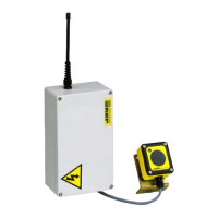
Anschlussklemmen Empfänger
UDR
* = entsprechend des Empfänger-Modells
Terminal number Function
3 x 1 to 12
Function relay board (A, B, C)
21
Power supply * :
Neutral / 0 v
22
Power supply * :
230VAC or 48VAC or 24VDC
23
Power supply * :
115VAC or 24VAC or 12VDC
24 - 25
Safety relay n°1 (RS1)
26 - 27 Safety relay n°2 (RS2)
28 - 29
"Horn" relay (RK)
30 - 31 - 32
UDF
infrared module n°1
33 - 34 - 35
UDF
infrared module n°2
36 - 37 - 38
UDF
infrared module n°3
40 - 41
Auxiliary relay
(only present with certain additional
options)
UDR
receiver terminal strips
* = according to receiver model
Numéro de borne Fonction
3 x 1 à 12
Carte relais de fonction (A, B, C)
21
Alimentation* :
Neutre / 0 v
22
Alimentation*:
230VAC ou 48VAC ou 24VDC
23
Alimentation* :
115VAC ou 24VAC ou 12VDC
24 - 25
Relais de sécurite n°1 (RS1)
26 - 27 Relais de sécurite n°2 (RS2)
28 - 29
Relais "Klaxon" (RK)
30 - 31 - 32
Module infrarouge
UDF
n°1
33 - 34 - 35 Module infrarouge
UDF
n°2
36 - 37 - 38
Module infrarouge
UDF
n°3
40 - 41
Relais auxiliaire
(présent uniquement avec certaines
options additionnelles)
Borniers du récepteur
UDR
* = suivant le modèle du récepteur
A- Carte(s) relais (jusqu’à 3 cartes de 6 relais)
B- Tableau récapitulatif de la correspondance boutons-relais
C- Connecteur de la Carte liaison série RS232 (accessoire)
D- Carte relais auxiliaire (présente uniquement avec certaines
options additionnelles)
E- Presse étoupe passage câbles commande
F- Bornier du relais «Klaxon» (RK)
G- Bornier du relais de sécurité n°1 (RS1)
H- Bornier du relais de sécurité n°2 (RS2)
i- Passage câble alimentation récepteur
J- Bornier alimentation récepteur
K- Passage câble raccordement modules infrarouges UDF
L- Bornier des modules infrarouges UDF
V1- Voyant rouge "Code d'identité erroné + diagnostic"
V2- Voyant vert "Liaison radio établie + diagnostic"
V3- Voyant rouge du relais «klaxon» (RK)
V5- Voyant rouge des relais de sécurité (RS1 e RS2)
V4- Voyant d’alimentation du récepteur
F1- Fusible
F2- Fusible
Français
A- Relay board(s) (up to 3 relay boards with 6 relays)
B- Summary table of the buttons-relays correspondence
C- Connector for RS232 serial link board (accessory)
D- Auxiliary relay board connector (the board is present only with certain
additional options)
E- «Control» cable gland
F- «On/Horn» (RK) relay terminals strips
G- «Safety relay n°1» (RS1) terminals strips
H- «Safety relay n°2» (RS2) terminals strips
i- «Power supply» cable passage
J- «Power supply» terminal strips
K- «UDF infrared module» cable passage
L- «UDF infrared module» terminal strips
V1- red indicator light "wrong identity code + diagnostic"
V2- green indicator light "radio link established + diagnostic"
V3- «On/Horn» (RK) relay red indicator light
V5- «Safety relays n°1 and n°2» (RS1 and RS2) red indicator light
V4- «receiver power supply» red indicator light
F1- Fuse
F2- Fuse
English
A- Relaiskarte(n) (bis zu 3 Karten mit je 6 Relais)
B- Zusammenfassende Tabelle der Übereinstimmung Tasten - Relais
C- Anschluss der seriellen Verbindungskarte RS232 (Zubehör)
D- Hilfs-Relaiskarte (nur bei bestimmten Zusatzoptionen vorhanden)
E- Stopfbuchse für Durchführung der Steuerkabel
F- Klemme des "Hup"-Relais (RK)
G- Klemme des Sicherheitsrelais Nr.1 (RS1)
H- Klemme des Sicherheitsrelais Nr.2 (RS2)
i- Durchführung Versorgungskabel Empfänger
J- Klemme Empfängerversorgung
K- Kabeldurchführung Anschluss Infrarot-Module UDF
L- Klemme der UDF-Infrarot-Module
V1- Rote Kontrolllampe "Falscher Identitätscode + Diagnose"
V2- Grüne Kontrolllampe "Funkverbindung hergestellt + Diagnose"
V3- Rote Kontrolllampen des "Hup"-Relais (RK)
V5- Rote Kontrolllampe der Sicherheitsrelais (RS1 und RS2)
V4- Kontrolllampe Versorgung des Empfängers
F1- Sicherung
F2- Sicherung
Deutsch
 Loading...