- 90 - UD - 319472KFR EN DE
Micro n° 1
indicator light
V1
- RED -
Micro n° 2
indicator light
V2
- GREEN -
Possible causes of failure Possible remedies
- Melted fuses
- Wrong power supply wiring
- Internal electronic failure
- Check fuse state and calibre
- Check power supply wiring diagram according to
receiver model
or
- Contact the technical person in charge of the
installation
- Internal electronic failure
- Contact the technical person in charge of the
installation
2 flashes
3 flashes
4 flashes
5 flashes
6 flashes
7 flashes
Error messages
OFF
(Mainboard power supplied but power
supply red indicator light remains OFF)
Name and color of
indicator light
Mode Indication Message Status
No message reception OFF
Message reception with correct identity code OFF
Message reception with wrong identity code Regular flashes
Serial
link
"RS232 Mode" The receiver programming is in progress ON
No radio message reception OFF
Poor radio reception Flashing
Good radio reception ON
Serial
link
"RS232 Mode" OFF
Not activated (OFF) OFF
activated (ON) ON
Receiver switched OFF OFF
Receiver switched ON ON
Not activated (OFF) OFF
activated (ON) ON
Not activated (OFF) OFF
activated (ON) ON
All Indicates safety relays state
Normal
Indicates radio
reception quality
Microprocessor n°2
indicator light
V2
(GREEN)
Normal
Indicates validity
of identity code
Microprocessor n°1
indicator light
V1
(RED)
"Horn" relay ind.light
V3 (RED)
All Indicates "Horn" relay state
Function relays ind.light
(RED)
All
Indicates each function relays
state
Power supply ind.light
V4 (RED)
All
Indicates receiver power
supply state
Safety relays ind.light
V5 (RED)
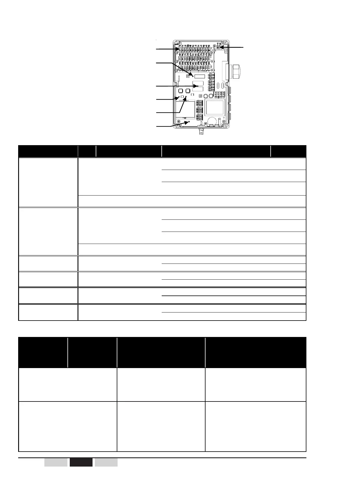
4.3.2 UDR indicator lights
Function relay indicator lights (red)
«Horn» relay indicator light (red) V3
«RS1 and RS2» safety relays
indicator lights (red) V5
Microprocessor n°1 indicator light (red) V1
Microprocessor n°2 indicator light (green) V2
Power supply indicator light (red) V4
Auxiliary relay
indicator light (red)
(the auxiliary relay is
present with certain
additional options)
 Loading...