- 70 - UD - 319472KFR EN DE
2.5.2- Marking of the controlled equipment,
If there are several equipment fitted with similar radio remote control systems working in the
same neighbourhood (e.g. in a plant), each transmitter shall carry a clear indication which
tells the equipment driver which equipment is controlled by the transmitter in question.
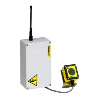
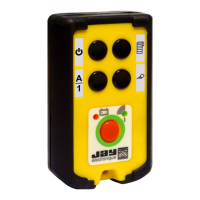
In this respect, signalling arrows are available as an accessory.
Place the different arrows on the equipment to be controlled so that each arrow colour
corresponds to that on the associated transmitter control button.
The direction of movement of control buttons shall whenever possible be consistent with
equipment motion. Symbols shall be fixed in such positions that there is a clear and unambiguous
relationship between the action on buttons in the control station and the corresponding direction
of motion.
The arrows are available in the following versions:
2.5.3- Wiring
If flexible stranded wire is used, crimped terminations should be used to avoid false contacts
and short circuits.
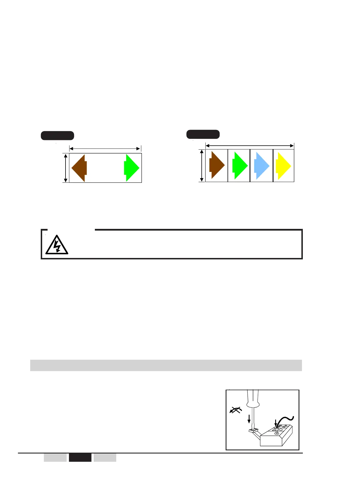
To open the connection terminal strips:
- Vertically push the screwdriver (flat tip screwdriver of 1.5 to
3 mm width) on the lever,
- Exercise a moderated pressure up to opening the terminal
- Insert the wire,
- Remove the screwdriver.
Wiring the receiver UDR
To avoid any risks of electrocution, do not open the receiver case
when powered.
WARNING
Important :
Do not place cables of different classes side by side.
A minimum space (20 cm) should be observed between the different classes :
- Class 1 : Radio, antenna cable (case of an antenna extension), connection of the UDF
infrared module (if the remote control is equipped with the option "starting up by
infrared validation").
- Class 2 : Mains for power supply of various units
- Class 3 : Power control for motors, variable speed drive, etc...
Ideally, each cable class should be run through a cable path specific to the class. If only one
cable path is available, cables of different classes should be separated as much as possible.
160
mm
400 mm
UWE001
Reference :
2 ways directional self-adhesive
color arrows
UWE002
Reference :
4 ways directional self-adhesive
color arrows
(independent arrows)
brown green brown green blue yellow
 Loading...