- 166 - UD - 319472KFR EN DE
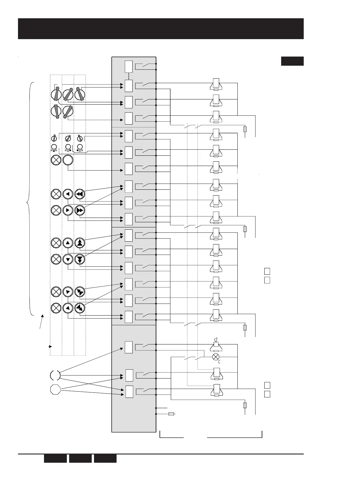
(*)= The power supply connection depends on the type of receiver and the power supply required.
(terminals 23 - 21 for power supplies 12VDC, 24VAC, 115VAC or 22 - 21 for power supplies 24VDC, 48VAC, 230VAC)
(**)=Relay life is increased by the use of surge limiters (ex: RC network for AC, Zener + diodes for DC etc...)
(**)= K1 and K2 contactors must have guided contacts
(**)= Elements wich indicate start of remote controlled machines (ex: horn, rotating / flashing light etc...)
*
**
U
C
L
C
NC
F
C
RA1
RS1 RS2
RK
RA2RA2 RA3 RA4 RA5 RA6
STOP
RB1 RB2 RB3 RB4 RB5 RB6 RC6
NEUTRAL
First speed
or notch n°1
Second speed
or notch n°2
23 22
U
D
R
27 26 29 28
U
1
L
1
U0F0
21
N1
F
1
U
A
L
A
NA
F
A
U
B
L
B
NB
F
B
K1 K2
K2
K1
K2
K1
1
(**) (**) (**)
*
U
D
E
25 24
**
(*)
UDR receiver
relays
Connection
terminals number
on UDR receiver
UDE transmitter
buttons
External driven
loads
External
wiring
example
1A 2A 3A 4A 5A 6A 7A 8A 9A 10A 11A 12A 1B 2B 3B 4B 5B 6B 7B 8B 9B 10B 11B 12B 1C 2C 3C 4C 5C 6C
On/Horn
1
2
1
.
Button number
Button postion
UDE transmitter
buttons action
on the UDR
receiver relays
K2
K1
1+2
1
2
1+2
UDR
pow.
supply
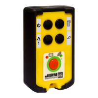
UDE022246 transmitter
RC1 RC2 RC3
11C 12C
K2
K1
Relay board B
Relay board A
Relay board C
Mainboard
nb.1
+
nb.2 nb.3 nb.4 nb.5 nb.6 nb.7 nb.8 nb.9 nb.10
Appendix ...........................................................D
Wiring example, transmitter UDE022246-011 with receiver UDR0CB00-011
EN
 Loading...