15
Operating and Maintenance Instructions
Front Panel – Booster
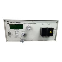
The front panel of the unit is shown in Figure 8 and described in Table 6.
Figure 8: Front of Amplifier (Booster)
Table 6: Operating Controls and LEDs
Control or LED Description
I/O LED indicator Power-on LED--an illuminated green LED indicates amplifier is
operating
EDFA STATUS Power-on pump laser LED--an illuminated green LED indicates
laser diode is active
Input Provides the input signal to the amplifier from optical signal
source
Output Provides the amplified output signal from the amplifier to the
device under test (DUT)
Laser Status LED
Cassette Power
Indicato
Out
ut A
erture
In
ut A
erture
 Loading...