64
Operation Manual
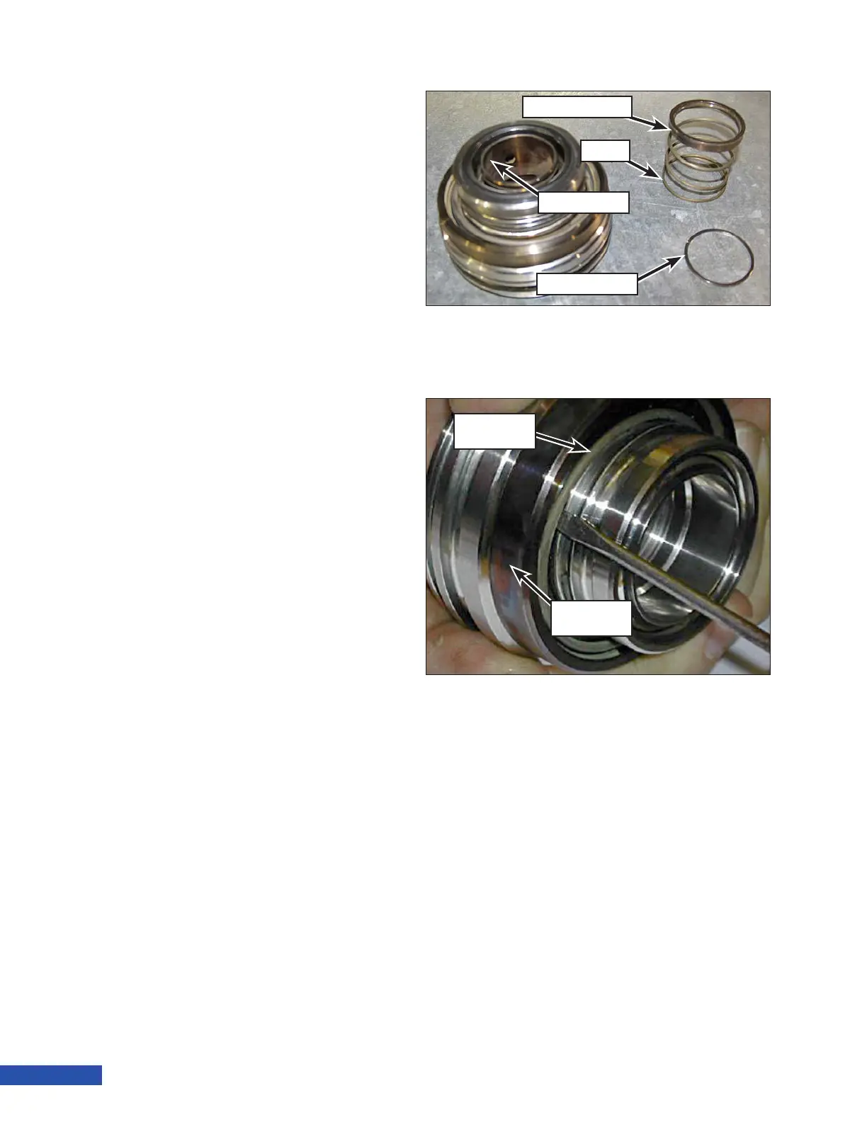
4. Remove the valve spring retainer and
valve spring (Figure 112).
5. Lift the assembly off of the suction valve
and set the suction valve aside.
6. Insert a small screwdriver under the dis-
charge spring (Figure 113). Carefully rotate
the screwdriver until the spring releases
from the groove.
Note: 3015 valves are equipped with a
retaining ring to secure the dis-
charge spring (Figure 114).
7. Remove the discharge valve and dis-
charge spring.
8. Inspect the valves. Refer to “Valve Inspec-
tion” on page 70 for inspection criteria.
Figure 112: Retaining Ring and Spring Removal.
Spring Retainer
Spring
Suction Valve
Retaining Ring
Figure 113: Discharge Spring and Valve Removal.
Discharge
Spring
Discharge
Valve