83
TwinForce™ Series Waterblast Unit
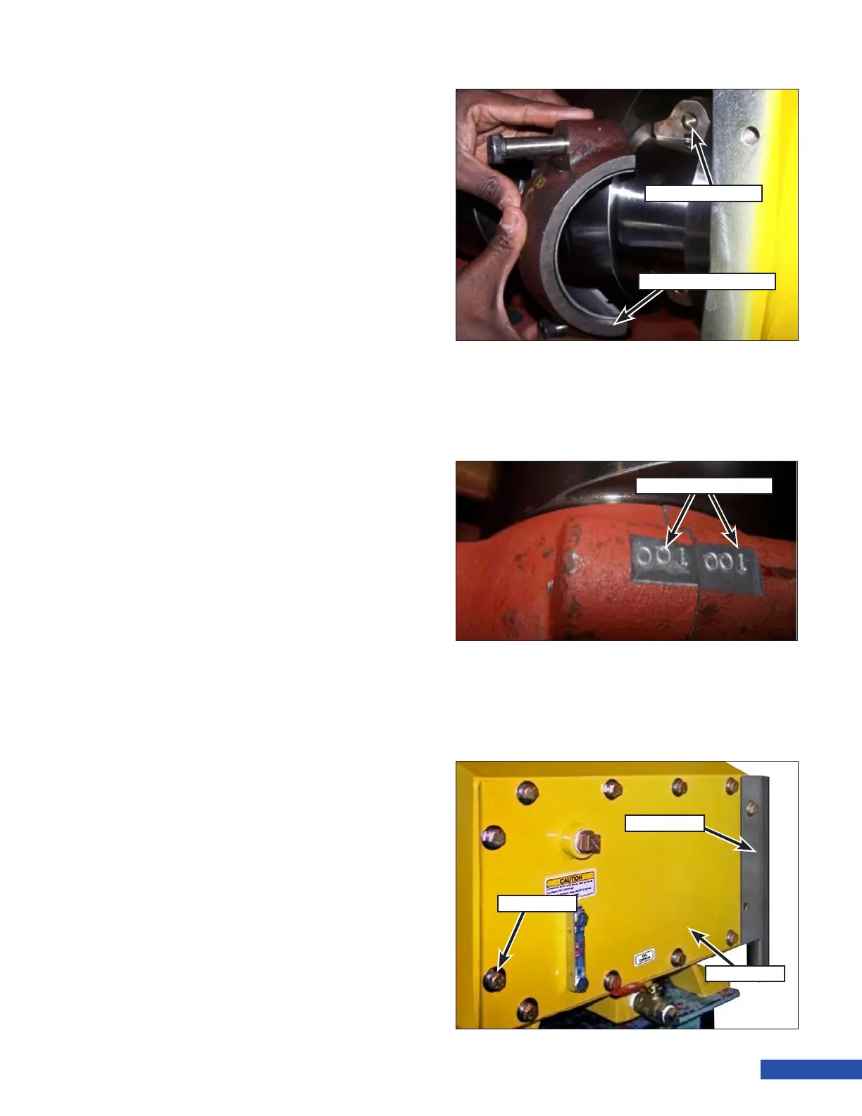
6. Pull the connecting rod (Figure 164) onto
the crankshaft and place the rod cap into
position aligned with the connecting rod.
Ensure the stampings (Figure 165) on the
cap and rod match.
7. Screw in the capscrews by hand and then
tighten to the proper torque:
• 3000 Series Pumps: 45 ft.lb (61 N·m)
• 3600/4200 Series Pumps: 80 ft.lb (108
N·m)
8. With the rst rod connected, rotate the
pump by pulling the belts. Allow the
crankshaft to turn a few revolutions to
ensure the rod was properly installed.
If the crankshaft spins freely, the bearings
were properly installed.
If the crankshaft does not spin freely, re-
move the journal bearings and replace with
another set.
9. Repeat the previous steps for installation
of the remaining journal bearings.
10. Place the back plate (Figure 166), belt
guard and gasket into position on the
frame.
11. Install the capscrews, lock washers and
at washers. Tighten the capscrews to the
proper torque.
• 3000 Series Pumps: 20 ft.lb (27 N·m)
• 3600/4200 Series Pumps: 35 ft.lb (47
N·m)
12. Fill the power end with oil as outlined in
“Changing the Power End Oil” on page
73.
Figure 164: Rod Cap Installation.
Rod Cap & Bearing
Connecting Rod
Figure 165: Matched Parts Stampings.
Rod Cap & Bearing
Belt Guard
Back Plate
Cap SCrew
Figure 166: Cover Plate Installation.