85
TwinForce™ Series Waterblast Unit
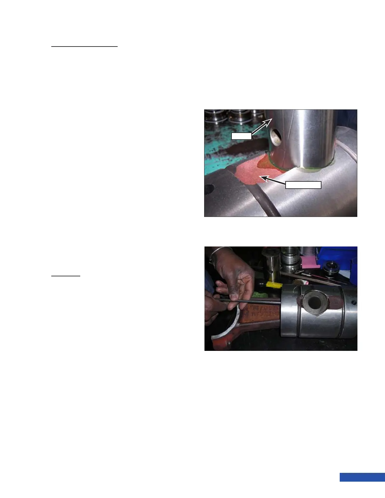
Figure 169: Pin Placement.
Figure 170: Second Set Screw Installation.
Pin
Crosshead
Crosshead Inspection
1. Use a micrometer to measure the outer
diameter of the crosshead in three places
and record the measurements.
2. Add the three measurements and divide
by 3 to get the average diameter.
3. Use an inside micrometer to measure
the crosshead bore in the power frame
in three places and record the measure-
ments.
4. Add the three measurements and divide
by 3 to get the average diameter.
5. Subtract the diameter of the crosshead
from the inside diameter of the cross-
head bore. If the remainder is greater than
0.012 in. (0.31 mm), the crosshead must
be replaced.
Note: New part clearances are as fol-
lows:
• Series 3000: 0.004 in. (0.1 mm) - 0.007
in.(0.2 mm)
• Series 3600/4200: 0.006 in. (0.15 mm) -
0.009 in. (0.23 mm)
6. Repeat for the remaining assemblies.
Assembly
1. Clean all surfaces of the crossheads, pins,
and connecting rods using brake cleaner.
2. Inspect all surfaces of the crossheads,
pins, and connecting rods for any signs of
damage. Replace any suspect or damaged
parts.
3. Inspect the long bore oil passage through
the length of the connecting rod. Use a wire
or a long handle brush to clear passage if
necessary.
4. Insert the connecting rod into the bottom
of the crosshead and line up the bores.
5. Lubricate the pin (Figure 169) with clean
oil and insert the pin into the hole in the
side of the crosshead.
6. Align the hole in the connecting rod with
the pin as it is slipped in.
7. Thread the rst set screw into the cross-
head hole until it touches the pin, then
back off a 1/4 turn. Slide the pin into posi-
tion and tighten the set screw ensuring
the screw is engaged in the counterbore
of the pin. Tighten the set screw to 30 ft lb
(41 N·m).
8. Apply Loctite Red-271© onto the threads
of the second backup set screw.
9. Install the second set screw on top of the
rst set screw. Tighten to 36 ft lb (49 N·m)
(Figure 170).
10. The crosshead is now ready for installa-
tion in the pump.