SECTION 3 - CHASSIS, PLATFORM & SCISSOR ARMS
3-4 – JLG Lift – 3121325
SECURE MACHINE WITH JACKS AND CHALK BLOCKS WHEN
REMOVING AND/OR INSTALLING WHEELS.
NOTE: Follow these steps when servicing/replacing the
wheel/tire assembly.
Removal
1. Elevate machine with jacks or other suitable device
and secure.
1. Remove 6 Wheelnuts (1).
2. Carefully remove tire from Drive Hub (2).
3. Disconnect all hoses/wires from Drive Motor (5).
4. Unscrew Capsrews (7) on Valve (6) and carefully
remove valve.
5. Remove two Bolts (6) and Lockwashers (7) attach-
ing the Drive Motor to the Drive Hub. Carefully
remove the Drive Motor.
6. Remove the eight Bolts (3) and Flatwashers (4)
attaching the Drive Hub to the Spindle (8). Carefully
remove the Drive Hub.
Installation
• Follow the removal steps in reverse order when install-
ing the wheel assembly.
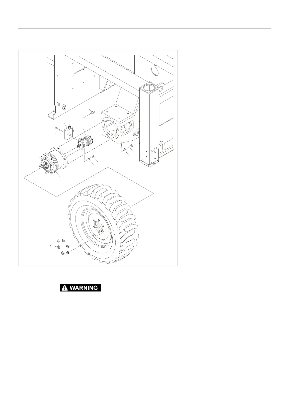
Figure 3-2. Wheel Assembly Removal
1. Wheel Nut (6 per tire)
2. Drive Hub
3. Bolt, M16 x 55mm (6 per wheel)
4. Flatwasher, M16 (6 per wheel)
5. Capscrew, M16 x 35mm
(2 per wheel)
6. Double Shock Valve (Rear Wheels)
Travel Brake Valve (Front Wheels)
(Not Shown)
7. Capscrew, M10 x 45mm (Rear)
(4 per valve)
Capscrew, M10 x 55mm (Front)
(Not Shown) (4 per valve)
8Drive Motor
9 Bolt, M12 x 35mm (2 per motor)
10 Lockwasher, M12 (2 per motor)
 Loading...