PowerBoost DC Converter System 1.5: Quick Start Guide
16995-01 rev. D
This document contains proprietary information. No part of this document should be reproduced
or distributed beyond its intended recipients without the express written consent of JMA Wireless. 16
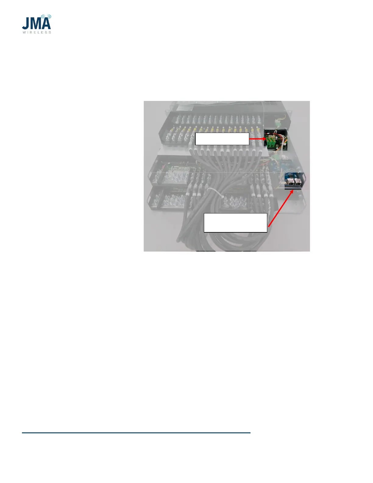
4.4. RS485 Data link and alarm connections
4.4.1. RS485 data
Alarm connections are made
in the location shown. See
further below for more
information.
OVP data connection is made
in the location shown. This is
the PowerBoost “VBOOST
IN” connection. The lower
OVP “VBOOST OUT” connects
here.
Note: If PowerBoost has 2
connectors (as shown in
photo):
• Connection to either
connector is acceptable.
• Only 1 cable connects tothis location; both connectors are never used at same time.
 Loading...