PowerBoost DC Converter System 1.5: Quick Start Guide
16995-01 rev. D
This document contains proprietary information. No part of this document should be reproduced
or distributed beyond its intended recipients without the express written consent of JMA Wireless. 12
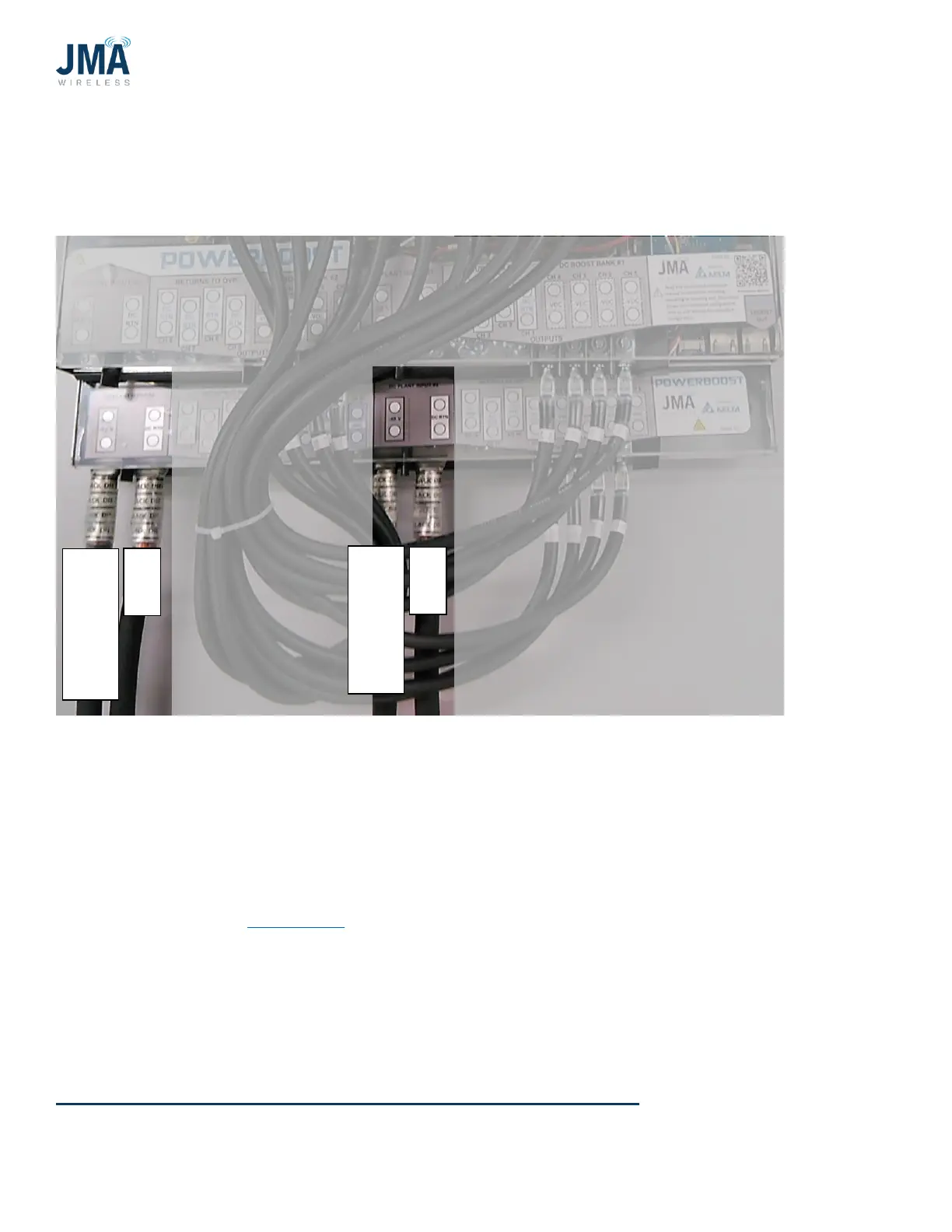
Photo below shows PB-19-SYS-16. Power inputs #1 and #2 are the same as shown in PB-19-
SYS-8 above. PB-19-SYS-16 only: LOWER SHELF Power inputs #3 and #4.
4.3. Connect PowerBoost outputs to lower OVP
• Output wiring and overcurrent protection must be installed in accordance with all local and
national electric codes and requirements.
Torque value for all lugs on the PowerBoost unit is 65 lbf·in. See labels on lug covers for
further detail. See Appendix C for reference information connections to lower OVP rack.
 Loading...