The mounting bracket is used to mount the unit inside the cab. Normally it is mounted onto the
driver's A-post. However, it is also possible to mount it onto the driver's right arm rest. This is
ideal for snow ploughs.
User Interface
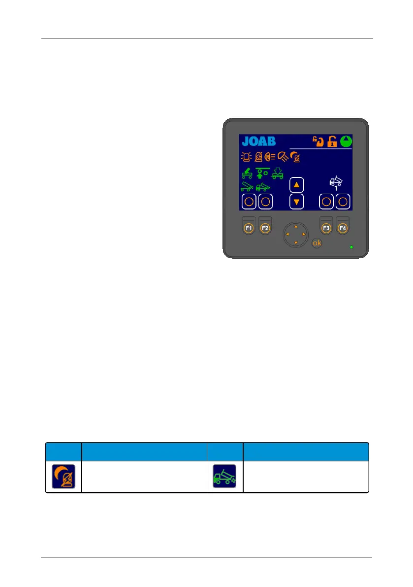
Shown opposite is an overview of the user inter-
face.
The areas marked with a white rectangle on the
screen are programmable. The user can set
which functions are placed there. These func-
tions are activated by pressing the cor-
responding buttons: F1–F4 and the UP/DOWN
arrows. For further information on how to set
these functions, refer to "Function Buttons", on
page 14 below.
The function icons (F1–F4 and the UP/DOWN
arrow buttons) that are displayed in the user
interface is dependent upon which page set-up
is selected. There are four different page set-
ups. To switch between these press either the left or right arrow button located below the
screen. For more information see "Page Set-Ups", on page 13.
All other icons that are displayed on the screen (not the user defined functions) simply provide
feedbackto the user regarding the status of the hook-lift, which page set-up is active, and active
functions, such as lights on etc.
Icons
Provided below is a list of the functions available in the user interface and their meaning. Note,
not all functions listed below are activated for all installations. Some of the functions are optional
extras, these are marked with an asterisk (*).
Functions that can be selected for the programmable areas (F1–F4 and the UP and DOWN but-
tons) are coloured white. All other buttons (orange and green) simply provide feedback to the
user as to whether or not they are active.
Icon Function Icon Function
Night mode Spreader flap – VEHICLE*
Table 1: User interface – icon description
12
Operation – Electrical Systems | CBW controller
Hookmaster manual: 13293 Edition 6 | 2021-02-22