Operation – Air Systems
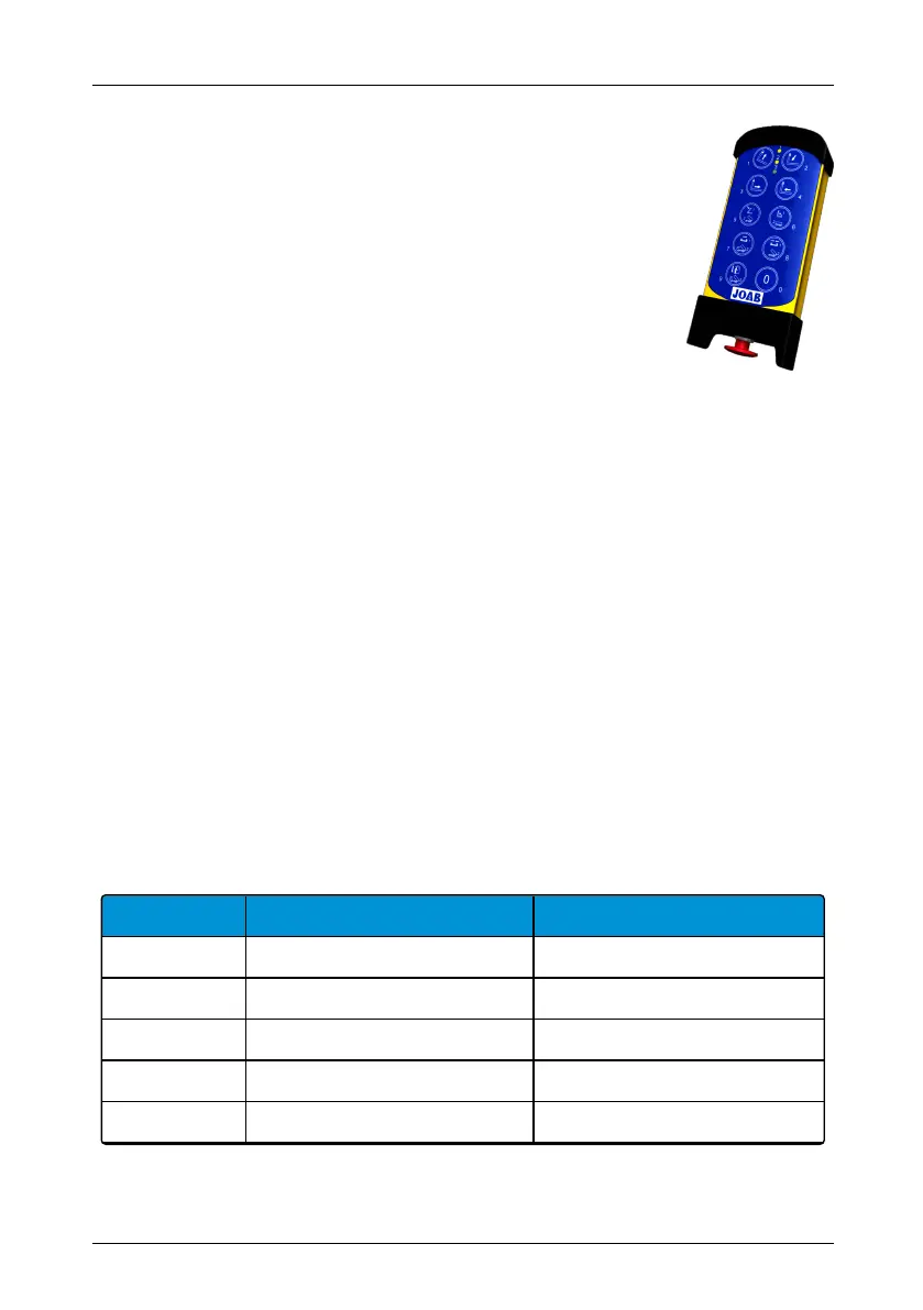
Provided below is an overview of the radio controller for air controlled
hook-lift systems.
Operation of the hook-lift is made using the main control buttons 0-9, as
shown opposite.
LEDs
There are three LEDs at the top of the controller. Two yellow (1 and 2)
and one green (3). LEDs 1 and 2 indicate which function mode is selec-
ted, refer to "Function Mode", on page 27 below.
LED 3 is lit green when the controller is active and red when the battery is low.
Emergency Stop
The large red emergency STOP button located at the bottom of the controller is used to stop the
hook-lift in an emergency. To activate it, simply push it in. It must be pulled out to start the con-
troller.
Function Mode
LEDs 1 and 2 (yellow) indicate which mode the controller isin. Either Function_1 or Function_2.
Buttons 5–9 have the numbers 1 and 2 written on them and have two functions. These are
related to the function mode selected for the controller (Function_1 or Function_2).
To select the desired function mode, simplypressbutton 0 after start-up of the controller, until
LED 1 or LED 2 isilluminated.
Listed below are the radio controller's buttons and their functions in relation to which function
mode has been selected.
Button Function mode 1 Function mode 2
1 Tip UP Tip UP
2 Tip DOWN Tip DOWN
3 Sledge backwards Sledge backwards
4 Sledge forwards Sledge forwards
5 Hook-post – UP Trailer tip – UP
Table 9: Remote control functions for pneumatically controlled systems
27
Radio Controllers | Operation – Air Systems
Hookmaster manual: 13293 Edition 6 | 2021-02-22