Information regarding operation is displayed in the controller's display, located at the top of the
controller.
Buttons 1–8 are analogue. Pressing these buttons harder will cause the operation that it con-
trols to happen faster. Alternatively, these buttons can be set to simply have an ON/OFF func-
tion.
Buttons 9–12 are digital and used for simple functions, such as the operation of a spreader flap.
The buttons 1–12 are multifunctional. That is, they can have more than one function assigned to
them. See "Function Mode", on page 25 below.
Display
The display at the top of the controller displays information regarding the current function mode
selected and the function currentlyactivated. In the example shown, the truck symbol indicates
that function mode_1 isselected and that the current function being operated is the hydraulic-
lock.
LEDs
Each button has an LED located to the left or right of it. In the example shown, the LED to the left
of button 2 isilluminated green. These LEDs are used to provide information regarding current
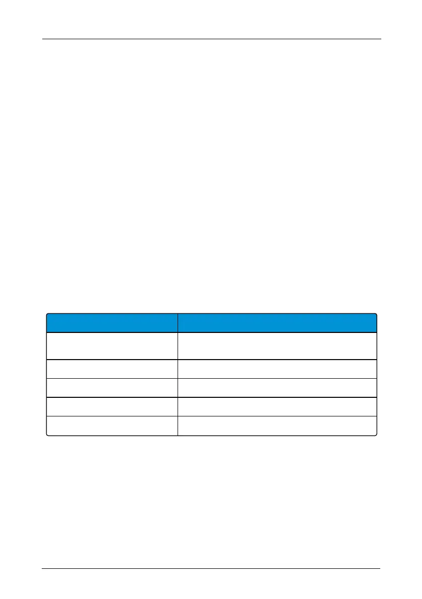
status of the active operation. Listed below is table describing what each relevant LED means.
Indicator lamp for button
Meaning green indicator lamp
2
Tip DOWN completed. Lock or unlock the hydraulic
lock.
4 The sledge is at the rear most point of the Hookmaster.
8 Hydraulic lock is OPEN. The body cannot be tipped UP.
12 Function mode 2 selected.
11 and 12 Function mode 3 selected.
Table 7: Indicator lamps and their meaning
Emergency Stop
The large red emergency STOP button located at the bottom of the controller is used to stop the
hook-lift in an emergency. To activate it, simply push it in. It must be pulled out to start the con-
troller.
24
Radio Controllers | Operation – Electrical Systems
Hookmaster manual: 13293 Edition 6 | 2021-02-22