FAC4911 physical features
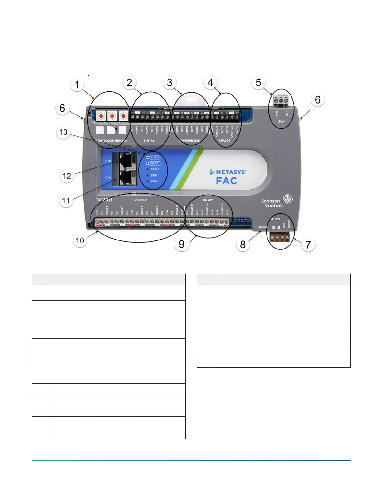
The following figure displays the physical features of FAC4911, and the accompanying table provides a description of the
physical features and a reference to further information where required.
Figure 1: Physical Features
Table 1: Physical features
Physical feature: description and references
1 Controller Number Rotary Switches: can be numbered
from 000 to 999. See Setting the Controller Number.
2 Binary Outputs (BO) Terminal Block: 24 VAC Triac. See I/
O terminal blocks, ratings, and requirements.
3 Configurable Outputs (CO) Terminal Block: 0–10 VDC
or 24 VAC Triac. See I/O terminal blocks, ratings, and
requirements.
4 Analog Output (AO) Terminal Block: Can be defined as
Voltage Analog Output (0–10 VDC) or Current Analog
Output (4–20 mA). See I/O terminal blocks, ratings, and
requirements.
5 24 VAC, Class 2/SELV Supply Power Terminal Block. See
Supply power terminal block.
6 Cover Lift Tab (One of Two)
7 SA Bus Terminal Block. See SA Bus terminal block.
8 Sensor Port: (SA Bus) RJ-12 6-Pin Modular Jack. See SA
Bus Port.
9 Binary Input (BI) Terminal Block: Dry Contact Maintained
or Pulse Counter/Accumulator Mode. See I/O terminal
blocks, ratings, and requirements.
Table 1: Physical features
Physical feature: description and references
10 Universal Inputs (UI) Terminal Block: Can be defined as
Voltage Analog Input (0–10 VDC), Current Analog Input
(4–20 mA), Resistive Analog Inputs (0–600kΩ), or Dry
Contact Binary Input. See I/O terminal blocks, ratings,
and requirements.
11 ETH2 Ethernet Port for BACnet/SC or BACnet/IP
Communications
12 ETH1 Ethernet Port for BACnet/SC or BACnet/IP
Communications
13 LED Status Indicators. See Troubleshooting Field
Controllers.
FAC4911 Advanced Application Field Equipment Controller Installation Guide2