FAC4911 model information
(including point type counts)
Table 2: FAC4911 model information (including point type counts)
Communication Protocol BACnet/SC or BACnet/IP
Supervisory Device All network engine model types at R9.0 or
later
Modular Jacks 6-Pin SA Bus with four communicating
sensors, 8-pin RJ-45 jack for Ethernet
connection
Point Types Signals Accepted Number of Points
Universal Input (UI) Analog Input, Voltage Mode, 0–10 VDC
Analog Input, Current Mode, 4–20 mA
Analog Input, Resistive Mode, 0–2k ohm,
resistance temperature detector (RTD)
(1k NI [Johnson Controls], 1k PT, A99B SI),
negative temperature coefficient (NTC) (10k
Type L, 2.252k Type 2)
Binary Input, Dry Contact Maintained Mode
10
Binary Input (BI) Dry Contact Maintained Mode
Pulse Counter/Accumulator Mode (High
Speed), 100 Hz
6
Analog Output (AO) Analog Output, Voltage Mode, 0–10 VDC
Analog Current Mode, 4–20 mA
4
Binary Output (BO) 24 VAC Triac 4
Configurable Output (CO) Analog Output, Voltage Mode, 0–10 VDC
Binary Output Mode, 24 VAC Triac
4
Mounting
Observe the following guidelines when mounting a field
controller:
• Ensure the mounting surface can support the
controller, DIN rail, and any user-supplied enclosure.
• Mount the controller horizontally on 35 mm DIN rail
whenever possible.
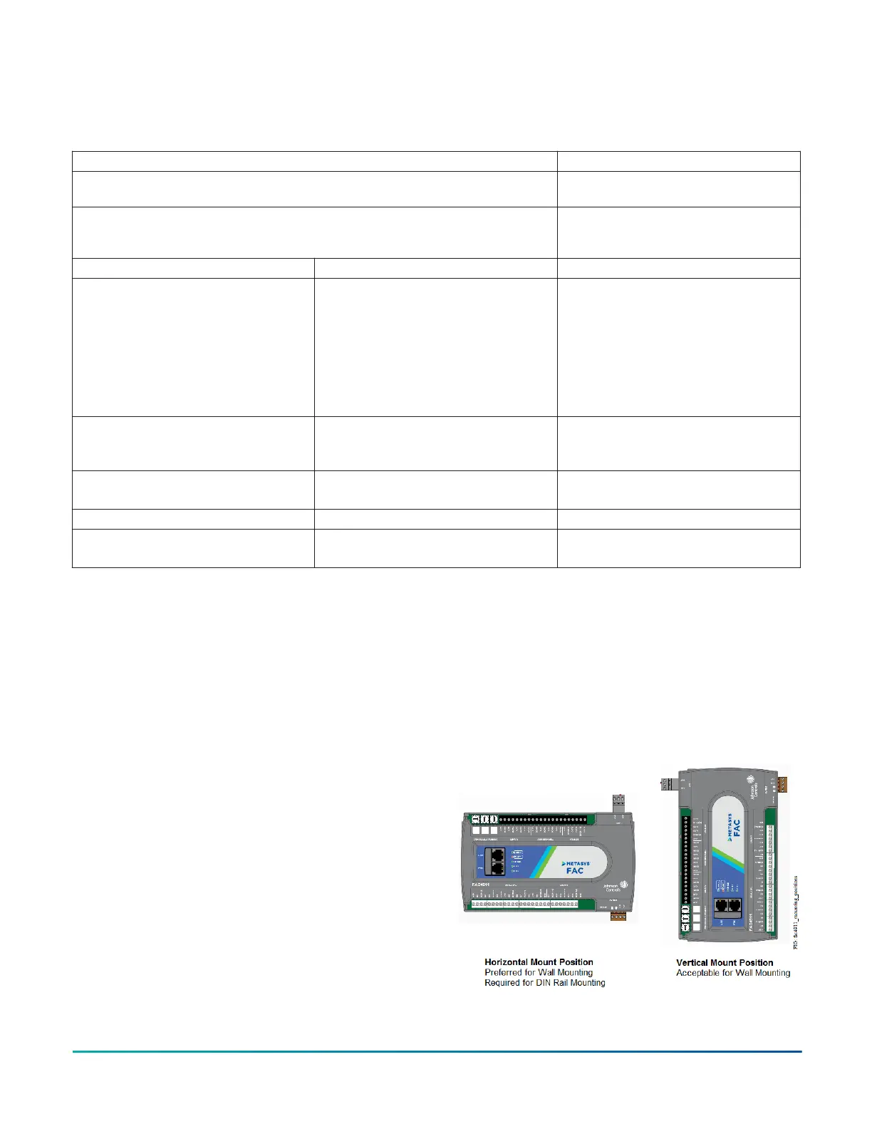
• Mount the controller in the correct mounting position
(Figure 2).
• Whenever possible in wall-mount applications, mount
the controller on a hard, even surface.
• Use shims or washers to mount the controller securely
and evenly on the mounting surface.
• Mount the controller in an area free of corrosive vapors
and observe the ambient conditions requirements in
Technical specifications.
• Provide sufficient space around the controller for
cable and wire connections, easy cover removal, and
good ventilation through the controller (50 mm [2
in.] minimum on the top, bottom, and front of the
controller).
• Do not mount the controller on surfaces prone to
vibration, such as ductwork.
• Do not mount the controller in areas where
electromagnetic emissions from other devices or wiring
can interfere with controller communication.
Observe these additional guidelines when mounting a
controller in a panel or enclosure:
• Mount the controller so that the enclosure walls do
not obstruct cover removal or ventilation through the
controller.
• Mount the controller so that the power transformer
and other devices do not radiate excessive heat to the
controller.
• Do not install the controller in an airtight enclosure.
Figure 2: Controller Mounting Positions
FAC4911 Advanced Application Field Equipment Controller Installation Guide 3