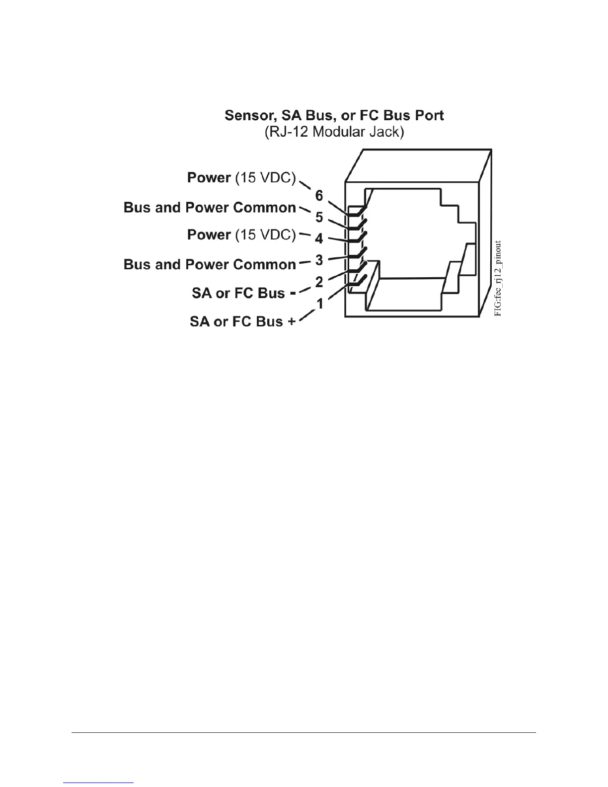
Figure 6: Pin number assignments for sensor, and SA bus ports on controllers
Sensor port
The Sensor (SA Bus) port on the bottom of the controller is an RJ-12, 6-position modular jack
that provides a connection for the Bluetooth Commissioning Converter, the VAV Balancing Tool,
specified network sensors, or other SA Bus devices with RJ-12 plugs.
When the FEC is configured for N2 communication, the SA Bus port must be used to download and
commission the controller. An FX-DIS Local Controller Display also can be connected to the SA Bus
port (but only on FX-PCG models without integral display and push buttons).
The Sensor port is connected internally to the SA bus terminal block. See Table 6 for more
information. The Sensor Port pin assignment is shown in Figure 6.
Supply power terminal block
The 24 VAC supply power terminal block is a gray, removable, 3-terminal plug that fits into a board-
mounted jack on the top right of the controller.
Wire the 24 VAC supply power wires from the transformer to the HOT and COM terminals on the
terminal plug as shown below. The middle terminal on the supply power terminal block is not used.
See Table 6 for more information about the Supply Terminal Block.
9FX-PCG26 General Purpose Programmable Controller Installation Instructions