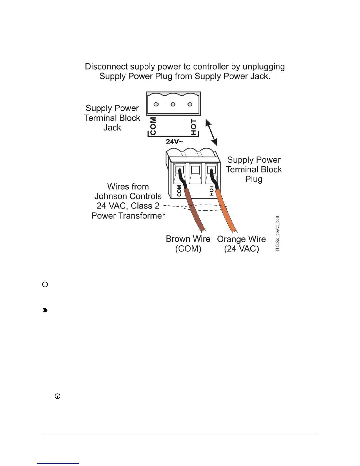
Figure 7: 24 VAC supply power terminal block wiring
Note: The supply power wire colors may be different on transformers from other
manufacturers. Refer to the transformer manufacturer’s instructions and the project
installation drawings for wiring details.
Important: Connect 24 VAC supply power to the controller and all other network devices so
that transformer phasing is uniform across the network devices. Powering network devices
with uniform 24 VAC supply power phasing reduces noise, interference, and ground loop
problems. The FX-PCG does not require an earth ground connection.
Wireless network applications
The controller can also be installed in a wireless application using an FX-ZFR Wireless Field Bus
Router.
To configure a controller for use with the FX-ZFR Series Wireless Field Bus system:
1. Wire the input/output terminals and SA bus.
Note: In wireless network applications, do not connect any wires to the FC bus terminal
block. (Connect the SA/FC terminal block on a PCX to an SA bus only.)
2. Connect the FX-ZFR181x or FX-ZFR182x Wireless Field Bus Router to the FC bus port (RJ-12
FX-PCG26 General Purpose Programmable Controller Installation Instructions10