modular jack) on the front of the controller.
3. Ensure that the controller's device address DIP switches are set to the correct device address.
See Setting the device addresses.
4. Set DIP switch 128 to ON, which enables wireless operation on the FX-PCG.
For more information on the ZFR Pro Wireless Field Bus system, refer to the WNC1800/ZFR182x
Pro Series Wireless Field Bus System Product Bulletin (LIT-12012320).
For more information on the ZFR 1800 Wireless Field Bus system, refer to the ZFR1800 Series
Wireless Field Bus System Product Bulletin (LIT-12011336).
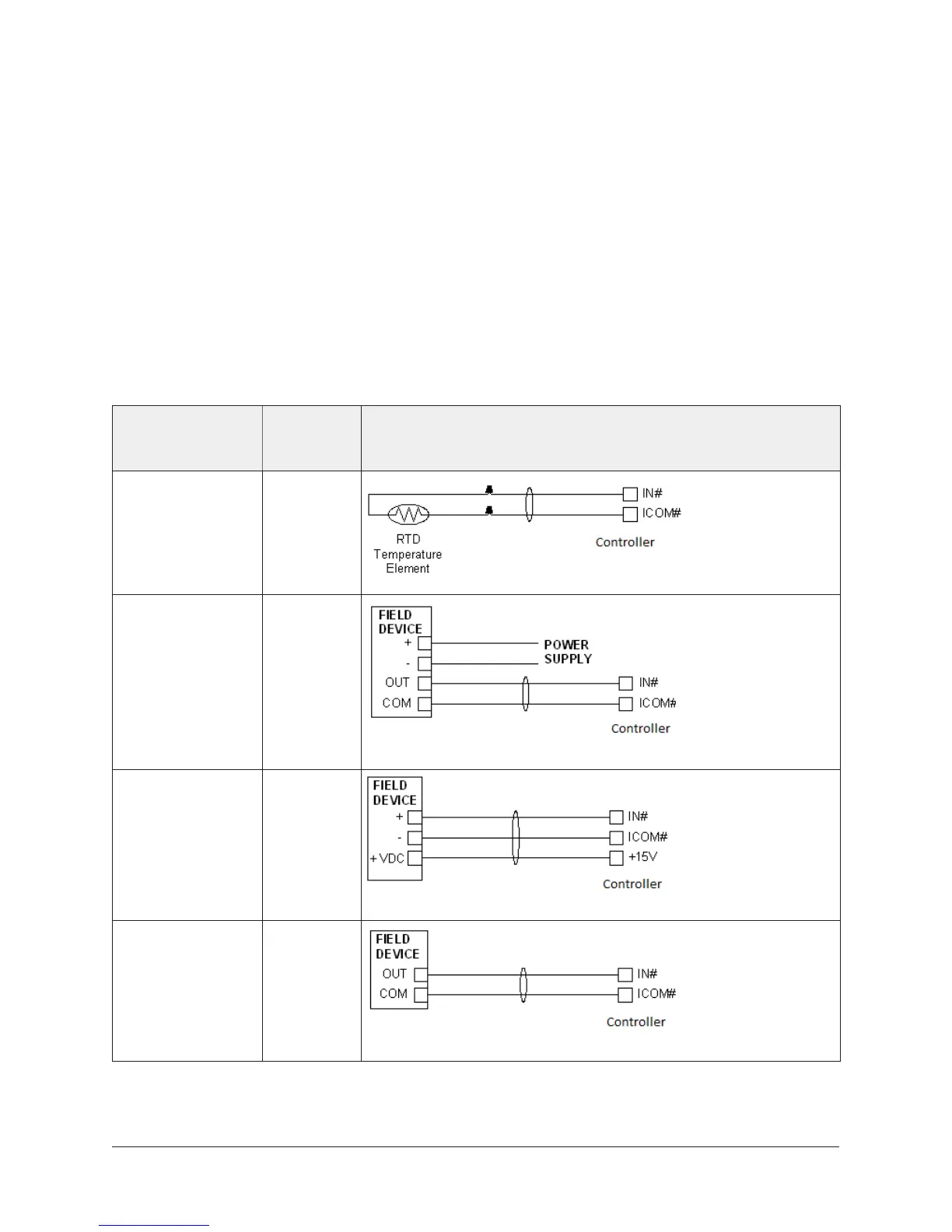
Termination details
A set of Johnson Controls termination diagrams provides details for wiring inputs and outputs to
the controllers. See the figures in this section for the applicable termination diagrams.
Table 2: Termination details
Type of field
device
Type of
Input/
Output
Termination diagrams
Temperature
Sensor
UI
Voltage Input -
External Source
UI
Voltage Input -
Internal Source
UI
Voltage Input
(Self-Powered)
UI
11FX-PCG26 General Purpose Programmable Controller Installation Instructions