Johnson Controls
Start-Up & Operation Guide | 5586996-JSG-A-0120
37
Operation
Variable Frequency Drives (VFDs)
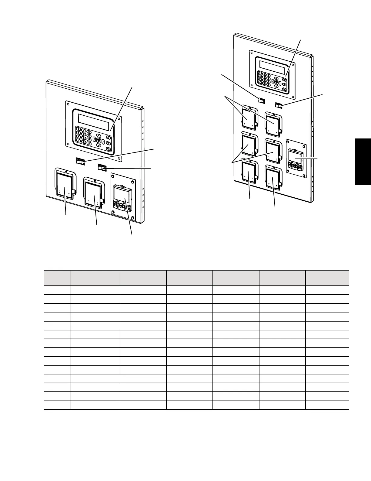
Depending on the options selected, the unit display panel
may have either three VFD cutouts or seven VFD cut-
outs. The cutouts either have a panel covering or a VFD
display installed that coincides with the unit's options.
Unit Enable
Switch
Condenser Fan VFD
UV Light
Reset Switch
LD28047
Figure 14: Three VFD Cutout Display Panel
User Interface
Unit Enable
Switch
Supply Fan
VFD(s)
Condenser
Fan VFD(s)
Compressor
VFD
Exhaust/Return Fan VFD
ERW VFD
UV Light
Reset Switch
NOTE: Depending on the VFD options selected for the unit, some
of the cutouts may have a blank plate covering instead of a
VFD display.
LD28048
Figure 15: Seven VFD Cutout Display Panel
Table 17: VFD Field Parameters
Address Function
Primary
Supply Fan
Secondary
Supply Fan
Return/Exhaust
Fan
Condenser Fan ERW
1-20 Motor Power Motor Specic Motor Specic Motor Specic Motor Specic Motor Specic
1-22 Motor Voltage Motor Specic Motor Specic Motor Specic Motor Specic Motor Specic
1-24 Motor Current Motor Specic Motor Specic Motor Specic Motor Specic Motor Specic
1-25 Motor Nom Speed Motor Specic Motor Specic Motor Specic 1140 1140
3-02 Min Reference 0 0 0 0 0
3-03 Max Reference Note 1 Note 1 Note 1 60 60
3-41 Ramp Up Time 30 30 30 5 30
3-42 Ramp Down Time 30 30 30 5 30
4-12 Motor Hz Low Lim 9 9 9 6 9
4-14 Motor Hz Hi Lim Note 1 Note 1 60 60 60
4-19 Max Out Freq Note 2 Note 2 63 63 63
6-14 AI Min Ref 0 0 0 0 0
6-15 AI Max Ref Note 3 Note 3 60 60 60
8-31 Modbus Address 1 2 3 1 5
NOTES:
1. Max Referance and Motor Hz Hi Limit parameters are set to 5% less than the Max Out Freq.
2. Max Out Freq is specic to the fan used in the unit. It is set to the fan's maximum RPM limit and locked from user adjustment to prevent
unsafe operating conditions.
3. AI Max Ref is unit specic and calculated based on the the user requirements for airow and static air pressure.