Johnson Controls
Start-Up & Operation Guide | 5586996-JSG-A-0120
55
Operation
• When ame rectication is established, the con-
troller enters a warm-up cycle to ensure ame sta-
bilization and to reduce condensation forming in
the heat exchanger
• After completing the warm-up cycle, the controller
enters the run cycle
• During the run cycle, the burner firing rate
and draft inducer pressure are determined
based on the heating demand sent via Mo-
dus from the unit controller
• The unit controller determines when more
or less heating capacity is needed and com-
municates this via Modbus to the modulating
gas controller
• The run cycle terminates when
• The heating demand is removed
• Any of the gas heat safeties open
• The control reaches its maximum runtime
of 6 hours. When this limit is reached, the
control terminates the run cycle and im-
mediately re-enters heating operation
when a heating demand still exists
• After terminating the run cycle, the 2-stage gas
valve closes and the modulating gas valve returns
to a set position
• The inducer is controlled to the light-off setting for
a 45-second post-purge cycle
• After completing the post-purge cycle, the control-
ler enters the off cycle. In the off cycle, all outputs
are de-energized but all safeties are still monitored
• When more heating capacity is needed, the unit
controller starts staging on other burners (2, 3, or
1B)
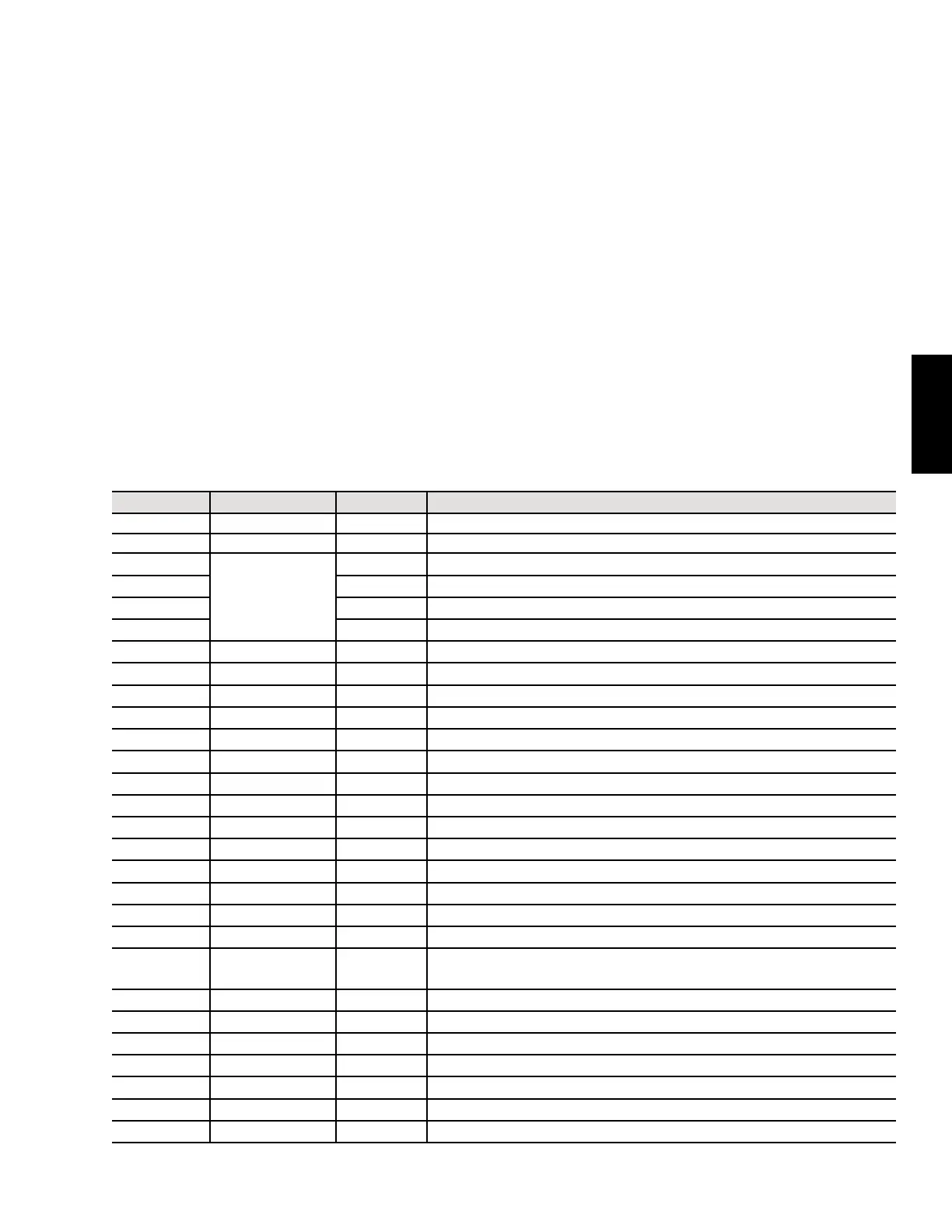
Table 24: Modulating Gas Heating Faults List
LED Display Diagnostic Code Type Description
888 1 Lockout Board failure (also during power up)
OFF 2 Status UP mode: burner state = OFF
Pur
3
Status UP mode: burner state = Purge
16n Status UP mode: burner state = Ignition
HEA Status UP mode: burner state = Warm-up
run Status UP mode: burner state = Run
rEt 4/5 Status UP mode: burner state = Retry
A01 4 Alert Failed ignition attempt
A02 5 Alert Lost ame
A03 6 Alert Insufcient combustion air—auto-derating
A04 7 Alert Limited low re (due to lost ame auto adaption)
A05 8 Alert Weak ame signal, main burner
A06 9 Alert Reserved
A07 33 Alert Air modulating failure (inducer isn’t modulating down)
A08 34 Alert Air sensor null pressure check (out of tolerance)
A11 24 Alert Failed ignition, split manifold burner, retries exhausted
A15 10 Alert Weak ame signal, one or more split manifold staged burners
E01 11 Lockout Failed ignition, retries exhausted
E02 12 Lockout Primary limit failure (or open fuse)
E03 13 Lockout Modulating valve failure
E04 14 Lockout
Air pressure sensor reading low (pressure switch failed to open or
insufcient air/blocked vent)
E05 15 Lockout Air pressure sensor reading high (pressure switch failed to close)
E08 18 Lockout Unexpected ame, main burner
E09 19 Lockout No R-W enable signal during CFH
E13 23 Lockout Open fuse
E18 22 Lockout Unexpected ame, split manifold burner
Ed 20 Lockout Invalid ID, plug installed
None None Lockout Board not receiving 24 volts