Johnson Controls
Start-Up & Operation Guide | 5586996-JSG-A-0120
39
Operation
LD28001
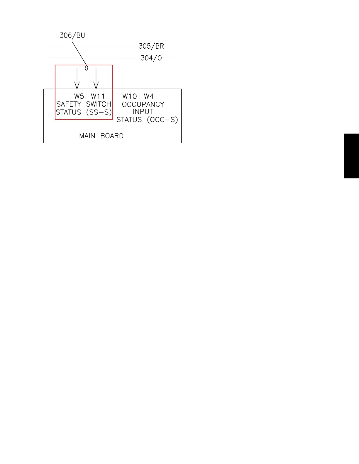
Figure 16: Safety Switch Input
Remote Safety Shutdown
The rooftop unit has a field input where a remote safety
shutdown circuit can be connected.
• When 24 VAC is applied to the safety switch input,
the unit operates normally.
• When 24 VAC is removed from the safety switch
input, the unit immediately shuts down, ignoring
any guaranteed on-timers.
There is a factory installed jumper between terminals
W5 and W11 on the main control board.
• To install any remote eld shutdown devices, re-
move the jumper between W5 and W11 and wire
all devices (dry contacts only) between these ter-
minals.
Low Voltage Monitoring
The unit controller continuously monitors the 24 VAC
control voltage circuit. The unit controller has two volt-
age limits programmed internally that cause preventive
actions to occur:
• 20.4 VAC: Before any relay output is turned ON,
the unit controller checks the 24 VAC circuit. If the
voltage is less than 20.4 VAC, no additional re-
lays are turned ON, and the appropriate alarm is
displayed
• 18 VAC: If the 24 VAC control circuit is 18 VAC or
less, the unit controller turns OFF all relay outputs
and displays the appropriate alarm
Supply Fan Operation
Every rooftop unit has a direct drive plenum (DDP)
supply fan. This type of fan does not have belts, drive
packages, or bearings.
All supply fans are controlled by a VFD. Control of the
supply fan is different depending on the unit type.
Supply Fan Alarm
All rooftop units have an air proving switch (APS). The
MZVAV configured units also have a factory installed
duct static pressure transducer.
The APS provides proof of operation for the supply fan.
Once the supply fan is started, the APS has 60 sec-
onds to close.
When the APS does not close within 60 seconds, the
following happens:
1. The unit controller immediately stops all cooling
or heating operation
2. Log the incident as a supply fan alarm
3. Start a 10 minute reset timer
4. After expiration of the 10 minute timer, the supply
fan attempts to restart
5. If a supply fan alarm occurs 6 times within 2
hours, the unit controller locks out the unit and
displays the unit locked out - airow proof alarm
When supply fan operation is proven and the APS
opens for more than 2 seconds, a supply fan alarm is
logged.
• Follow steps 1–5 above
MZVAV Supply Fan
When unit type is MZVAV, the supply fan runs when-
ever the unit occupancy is OCC. The supply fan speed
is controlled by the duct static pressure (DSP).
The DSP transducer sends a 0–10 VDC signal to the
unit controller. The unit controller uses this signal to
determine if the current DSP is higher or lower than the
DSP active setpoint.
• When the current DSP is below the DSP active set-
point, the unit controller increases the fan speed
• When the current DSP is above the DSP active set-
point, the unit controller decreases the fan speed
The unit controller outputs a 0–10 VDC signal to the
supply fan VFD. The DSP setpoint must be set under
the Views > Commissioning > Air Balancer > Supply
menu.