Johnson Controls
Start-Up & Operation Guide | 5586996-JSG-A-0120
43
Operation
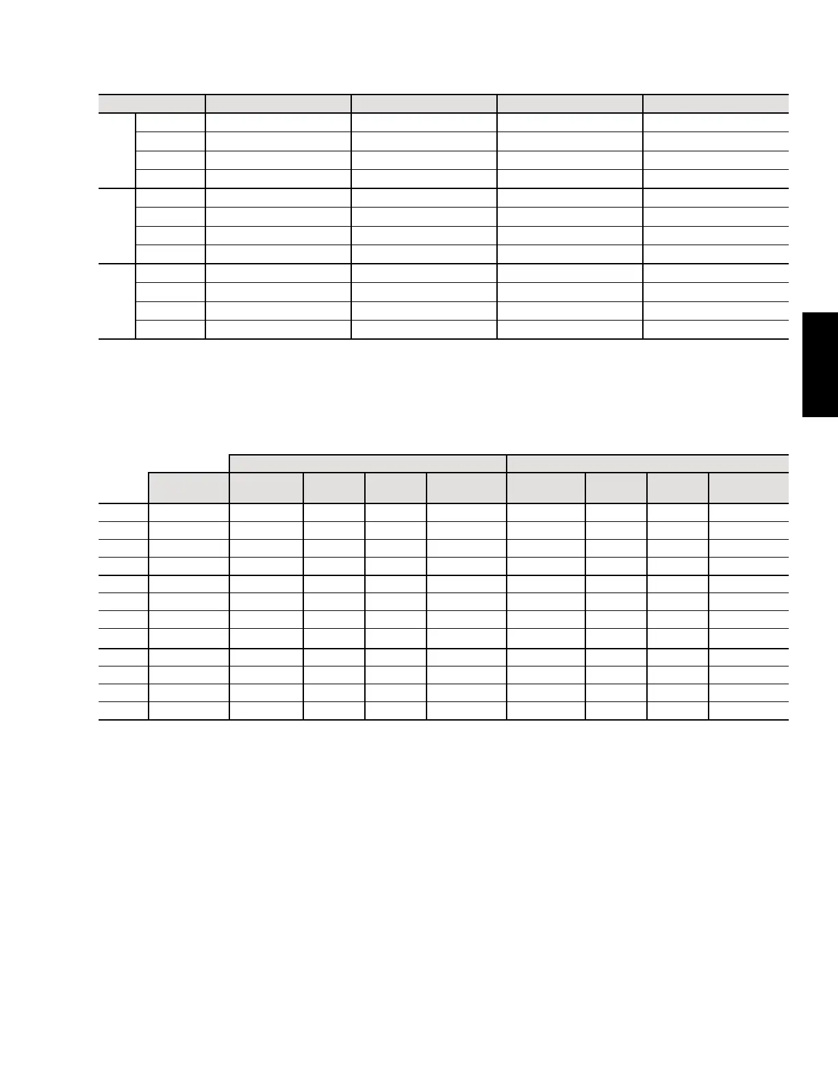
Table 18: Compressor Numbering
Unit Left Position
1
Mid-Left Position
1
Mid-Right Position
1
Right Position
1
Standard
Efciency
25 Ton 1A NA
2
2A 2B
30 Ton 1A 1B 2A 2B
40 Ton 1A 1B 2A 2B
50 Ton 1A 1B 2A 2B
High
Efciency
25 Ton 1A NA
2
2A 2B
30 Ton 1A NA
2
2A 2B
40 Ton 1B
3
1A
3
2A 2B
50 Ton 1B
3
1A
3
2A 2B
High
Capacity
25 Ton 1A NA
2
2A 2B
30 Ton 1A 1B 2A 2B
40 Ton 1A 1B 2A 2B
50 Ton 1A 1B 2A 2B
NOTES:
1. Facing the compressor end.
2. Not available.
3. On 40 and 50 ton high efciency units ONLY, the left position compressor is 1B and the mid-left compressor is 1A.
Table 19: Compressor Layout
Refrigerant Ckt 1 Refrigerant Ckt 2
Compressor
Manufacturer
Combination
Comp 1A
HP
Comp 1B
HP
Total Capacity
Ckt 1
Combination
Comp 2A
HP
Comp 2B
HP
Total Capacity
Ckt 2
25T SE Copeland Single 10 NA 10.0 Tandem 4.5 7 11.5
30T SE Copeland Tandem 7 7 14.0 Tandem 5.5 7.5 13.0
40T SE Copeland Tandem 11.5 5.5 17.0 Tandem 10 8.5 18.5
50T SE Copeland Tandem 7.5 15 22.5 Tandem 11.5 10 21.5
25T HE Copeland VSD Single 13 NA 13.0 Tandem 5 7.5 12.5
30T HE Copeland VSD Single 18.5 NA 18.5 Tandem 7 7 14.0
40T HE Danfoss VSD Tandem 13 10 23.3 Tandem 7.5 7.5 15.0
50T HE Danfoss VSD Tandem 17.5 12 29.5 Tandem 10 10 20.0
25T HC Copeland Single 10 NA 10.0 Tandem 5 7.5 12.5
30T HC Copeland Tandem 8.5 5.5 14.0 Tandem 7 7 14.0
40T HC Copeland Tandem 13 7 20.0 Tandem 10 8.5 18.5
50T HC Copeland Tandem 8.5 15 23.5 Tandem 7.5 15 22.5
NOTES:
VSD = Variable Speed Drive SE = Standard Efciency HE = High Efciency HC = High Capacity NA = Not Available
VSD Tandem = Comp 1A is VSD and Comp 1B is single speed
Single Speed Compressors
The rooftop units include single speed scroll compressors
as the standard offering. The single speed scroll compres-
sors can either be standalone or part of a tandem set.
Single speed scroll compressors are staged ON/OFF
to achieve and maintain the active DAT cooling set-
point. The unit controller contains logic that prevents
short-cycling of the compressors and also prevents
overshooting the active DAT cooling setpoint.
Variable Speed Compressors
The rooftop units can have a variable speed compres-
sor factory installed as an option. If a variable speed
compressor is ordered, it is always installed on refrig-
eration circuit #1 (compressor 1A). All other compres-
sors are single speed.
The variable speed compressor is always the first com-
pressor ON and the last compressor OFF.
The variable speed compressor is controlled by a fac-
tory installed VFD. The VFD is selected by the com-
pressor manufacturer and all programming is complet-
ed at the factory.