3-10
SM-18003
TROUBLESHOOTING
No. Item Data Name No. Item Data Name
1 b1 Set Temp. 22 H2 Suction Pressure
2 b2 Inlet Air Temp. 23 H3 Control Information
3 b3 Discharge Air Temp. 24 H4 Operating Frequency
4 b4 Liquid Pipe Temp. 25 J1 I.U. Capacity
5 b5 Remote Thermistor Temp. 26 J2 O.U. Code
6 b6 Outdoor Air Temp. 27 J3 System Number (1)
7 b7 Gas Pipe Temp. 28 J4 System Number (2)
8 b8 Evaporating Temp. at Heating 29 L1 I.U. Electronic Expansion Valve
9 b9 Condensing Temp. at Cooling 30 L2 O.U. Electronic Expansion Valve 1
10 bA Comp. Top Temp. 31 L3 O.U. Electronic Expansion Valve 2
11 bb Thermo Temp. of Wired Controller 32 L4 O.U. Electronic Expansion Valve B
12 bC Not Prepared 33 P1 Comp. Current
13 C1 I.U. Micro-Computer *
2
34 P2 Comp. Operating Accumulated Time
14 C2 O.U. Micro-Computer *
2
35 q1 Motion Sensor Reaction Rate *
1
15 d1 Stopping Cause State Indication 36 q2 Radiation Sensor Temp. *
1
16 E1 Times of Abnormality 37 q3 Motion Sensor 1 Reaction Rate *
1
17 E2 Times of Power Failure 38 q4 Motion Sensor 2 Reaction Rate *
1
18 E3 Times of Abnormal Transmitting 39 q5 Motion Sensor 3 Reaction Rate *
1
19 E4 Times of Inverter Tripping 40 q6 Motion Sensor 4 Reaction Rate *
1
20 F1 Louver Sensor State 41 q7 Setting Temp. Collected Value
21 H1 Discharge Pressure
Features of Check Mode 1
No. Item Data Name No. Item Data Name
1 q1 Inlet Air Temp. 9 q9 Discharge Pressure
2 q2 Discharge Air Temp. 10 qA Suction Pressure
3 q3 Liquid Pipe Temp. 11 qb Control Information
4 q4 Outdoor Air Temp. 12 qC Operating Frequency
5 q5 Gas Pipe Temp. 13 qd I.U. Expansion Valve
6 q6 Evaporating Temp. at Heating 14 qE O.U. Expansion Valve 1
7 q7 Condensing Temp. at Cooling 15 qF Comp. Current
8 q8 Comp. Top Temp.
Features of Check Mode 2
"C1" I.U. Micro-Computer State "C2" O.U. Micro-Computer State
1 Operation CMC1
2 Alarm RVR1
3 Heating Thermo ON CMC2
4 Cooling Thermo ON RVR2
5 - Outdoor Fan
6 - SVA
7 Drain-Up Mechanism SVB
NOTE:
Items for O.U. are different by O.U. model.
For detail, refer to the Service Manual for Outdoor Unit.
*
1
The average value for 30 seconds (update cycle time of Check Mode) is displayed on the LCD.
*
2
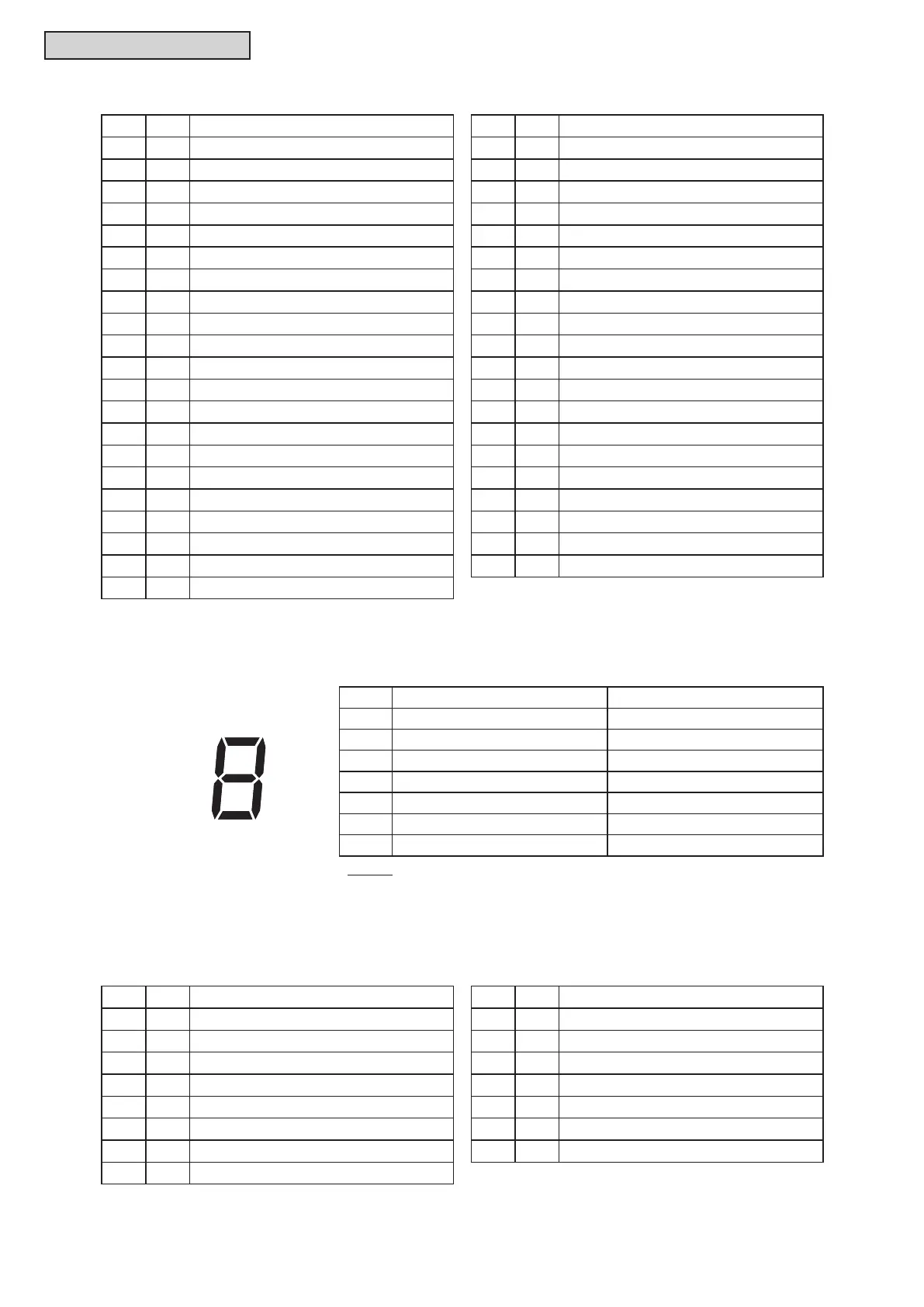
“C1” and “C2” are indicated by digital number like a 7-segment display.
Each signal means state of following item. (When ON, signal is displayed)
1
3
6

 Loading...