3-30
SM-18003
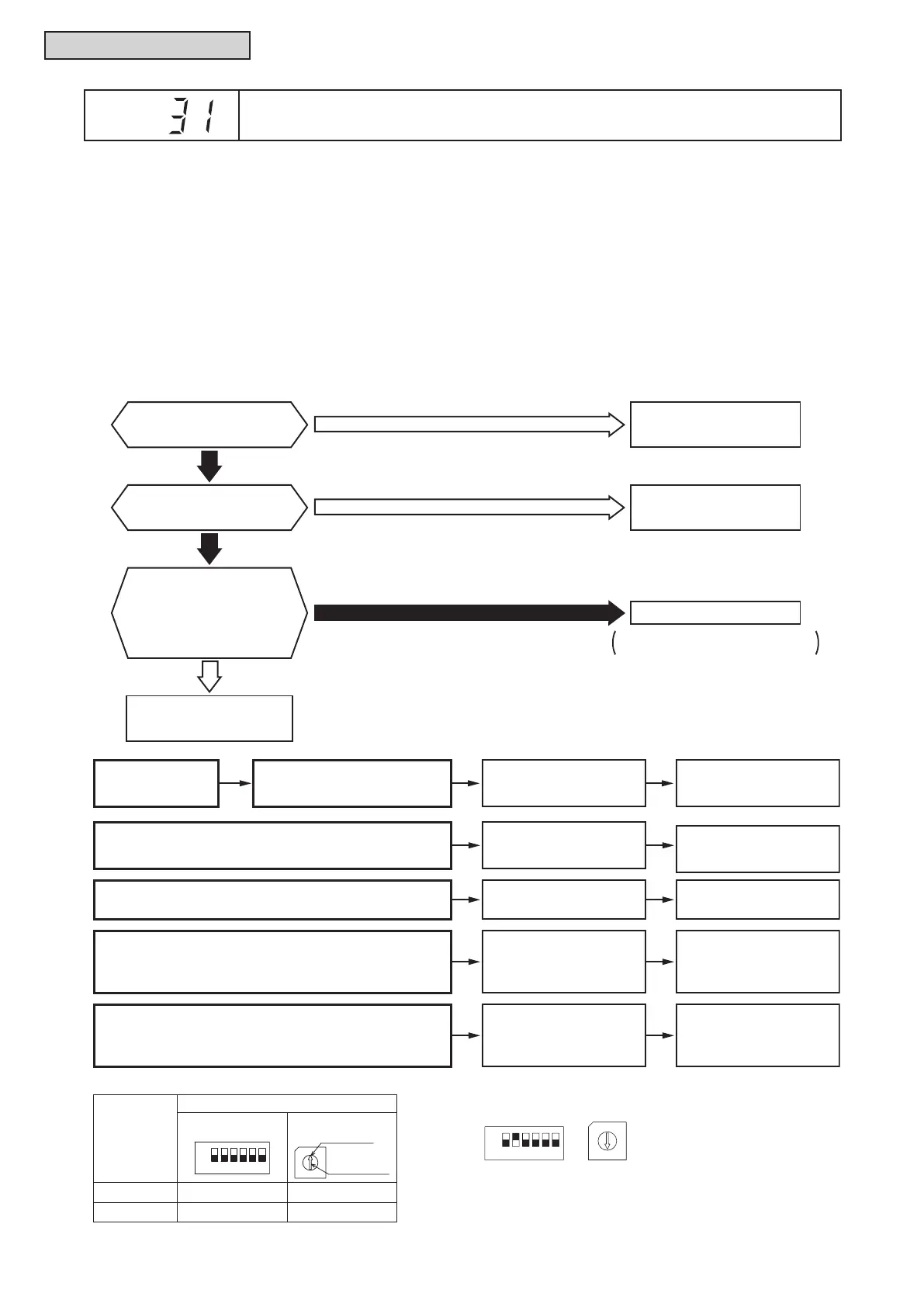
TROUBLESHOOTING
Are #1-#6 of DSW2 on
O.U. PCB set incorrectly?
Are the setting of
DSW1 and RSW1 on
O.U. PCB and setting
of DSW5 and RSW2 on
I.U. PCB totally same in
a refrigerant cycle?
Total indoor unit capacity
is wrong.
Set capacity of O.U. PCB.
No
Yes
Yes
Are #1-#4 of DSW3 on
I.U. PCB set incorrectly?
Set capacity of I.U. PCB.
No
Set them correctly.
No
Outdoor Unit PCB: DSW1, RSW1
Indoor Unit PCB: DSW5, RSW2
l
The RUN indicator (red) ashes.
l
The indoor unit number (refrigerant cycle number - address number), the alarm code, the model code
1
,
the model name
1
and the number of connected indoor units are displayed on the LCD. The alarm code
is displayed on the 7-segment display of the outdoor unit PCB.
Note 1: Except for some models.
1. This alarm code is indicated when the capacity setting DIP switch, DSW2, on the outdoor unit PCB, is not
set (all the settings from #1 to #6 are OFF) or set incorrectly.
2. This alarm code is displayed when the total indoor unit capacity exceed the connectable indoor unit
capacity ratio of outdoor unit.
Alarm
Code
Incorrect Capacity Setting of Outdoor Unit and Indoor Unit
Cause Check Item
Action
(Turn OFF Main Switch)
Event
Check combination of
indoor units and capacity
setting of I.U. PCB.
Correctly set DIP switch,
DSW3.
Incorrect Capacity Setting of Indoor Unit
Check outdoor unit
model by calculating
total indoor units
capacity.
Ensure that total
indoor unit capacity is
within permissible
range.
1
Total Indoor Unit Capacity Connected to
Outdoor Unit is Beyond Permissible Range
Check refrigerant cycle
setting of O.U. PCB
and I.U. PCB.
Set them correctly.
Refrigerant Cycle Setting of Outdoor Unit
and Indoor Unit is Different
Check capacity setting
of O.U. PCB.
Correctly set DIP switch,
DSW2.
Incorrect Capacity Setting of Outdoor Unit
DSW and RSW factory setting is 0.
Maximum in setting refrigerant cycle No. is 63.
Setting Switch
10 digit
32
ON
OFF
1 digit
0
7
9
8
6
4
3
1
2
Set by inserting
slotted screwdriver
into the groove.
Outdoor Unit DSW1 RSW1
Indoor Unit DSW5 RSW2
Example of Setting Refrigerant Cycle No.25
7
9
5
8
6
4
3
1
2
3214
ON
56
OFF
Turn ON No. 2 pin. Set Dial No.5.
O.U. PCB: Outdoor Unit PCB (PCB1)
I.U. PCB: Indoor Unit PCB
Refrigerant Cycle No. Setting
1: Refer to “Installation and Maintenance Manual” of outdoor unit for details.

 Loading...