3-48
SM-18003
TROUBLESHOOTING
Normal
Abnormal
The power source is not turned ON.
Back to (1) after checking
Wired Zone Controller
Indication
The operation light
flashes. (1 time/1 sec.)
And the Unit No. and
Alarm Code "03" flash.
The unit does not
start.
The connecting wires of operating
line are incorrect or loose.
The unit does not
start.
The connection of remote control
cable is incorrect.
This is the same as above items 1 through 3.
The unit does not
start, or starts once
and then stops.
The connection of the thermistors
or other connectors are incorrect.
Tripping of protector exists.
An authorized service person should check
the unit using the Alarm Code Table in this
manual.
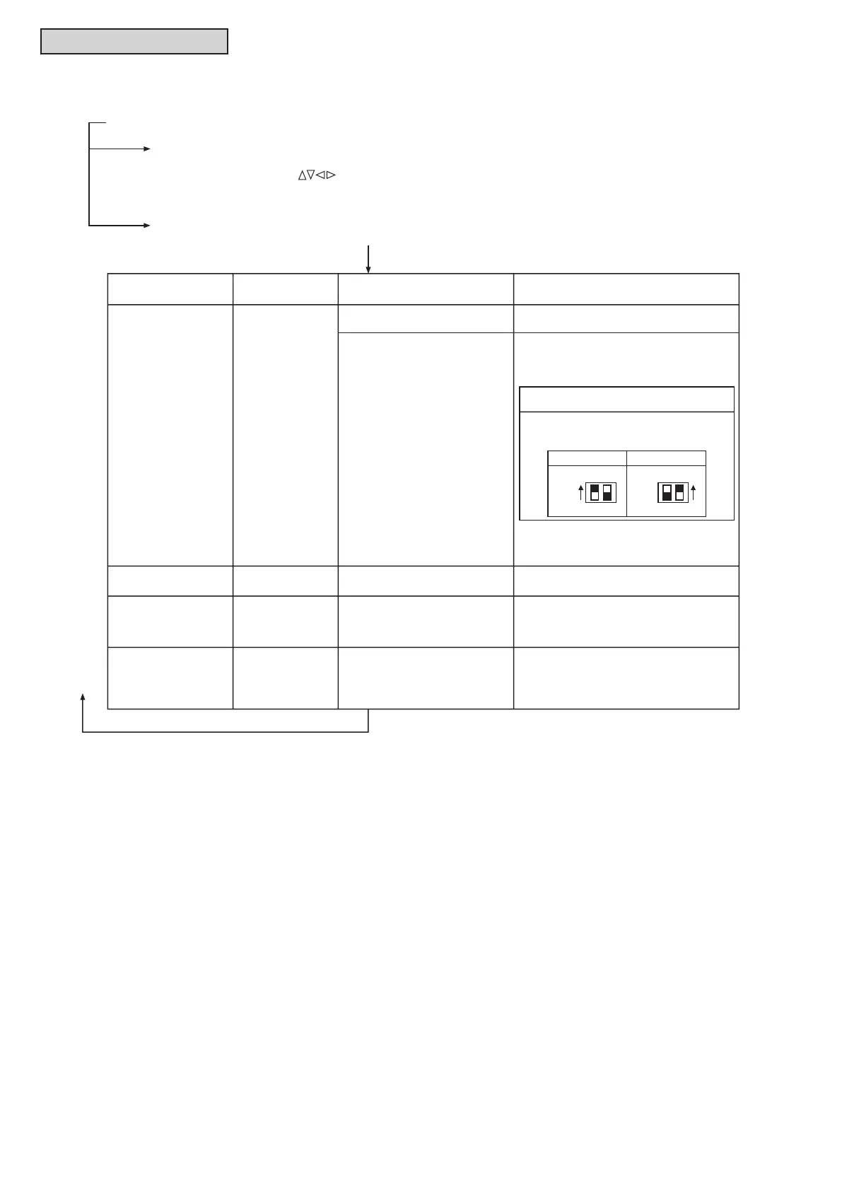
1. Connecting Order of each Te rminal Block.
The fuse on the PCB may be blown
due to miswiring. (Can be recovered only
once by the DSW on the PCB)
The operation light
flashes. (1 time/2 sec.)
Other alarm codes or
indications than those
above (Refer to
the alarm code table.)
Unit Condition Fault
Inspection Points when the
Power Source is OFF
Procedures for Recovery When Transmitting
Circuit Fuse is Blown
1. Correct the wiring for the terminal block.
2. Setting positions of the model code are
shown below.
2. Screw Fastening of each Te rminal Block.
3. Connecting Order of Power Line Between
Indoor Units and Outdoor Unit.
The unit does not
start.
The operation lamp
flashes. (1 time/1 sec.)
And the Unit No. 00.
Alarm Code dd and
Unit Code E.00 flash.
The connecting wires of operating
line are incorrect or loose.
An authorized service person should check
the unit using the Alarm Code Table in this
manual.
(5) Checking Procedure for Abnormalities
If the units do not start or the operation light on the wired zone controller flashes,
there is an abnormality.
Outdoor Unit PCB
Indoor Unit PCB
ON
OFF
1 2
DSW7
ON
OFF
1 2
DSW10
(4) Press “On/Off” switch.
The run test operation will be started. The operation mode, the airflow volume, the airflow direction
and the run test time can be set on the Te st Run screen.
Select the item by pressing “ ”.
The run test will be completed by pressing the “Back/Help” button during the stoppage or “On/Off” button
during the operation.
The test run operation will be started. The operation mode, the airow volume, the airow direction
and the test run time can be set on the Test Run screen.
The test run will be completed by pressing the “Back/Help” button during the stoppage or “On/Off” button
during the operation.
If the units do not start or the operation light on the wired controller ashes,
there is an abnormality.
Wired Controller
Indication
The connection of controller cable
is incorrect.
the Alarm Code Table.)
The operation light
button.

 Loading...