JOHNSON CONTROLS
6
FORM 160.78-N1
ISSUE DATE: 5/30/2012
LIST OF FIGURES
LIST OF TABLES
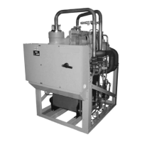
FIGURE 1 - YMC
2
Chiller Components .....................................................................................................................7
FIGURE 2 - Rigging.................................................................................................................................................13
FIGURE 3 - Neoprene Isolators ..............................................................................................................................15
FIGURE 4 - Neoprene Isolators ..............................................................................................................................16
FIGURE 5 - Spring Isolators ...................................................................................................................................17
FIGURE 6 - Spring Isolators ....................................................................................................................................18
FIGURE 7 - Typical Refrigerant Vent Piping ............................................................................................................19
FIGURE 8 - Schematic Of A Typical Piping Arrangement .......................................................................................20
FIGURE 9 - FAA Unit Insulation ..............................................................................................................................22
FIGURE 10 - FAB Unit Insulation ............................................................................................................................23
FIGURE 11 - Dimensions – 197 & 205 Compressor Units Ft-In (Mm) ....................................................................25
FIGURE 12 - Evaporators - Compact Water Boxes (1-Pass Nozzle Arrangements) ............................................. 26
FIGURE 13 - Evaporators - Compact Water Boxes (2-Pass Nozzle Arrangements) ............................................. 26
FIGURE 14 - Evaporators - Compact Water Boxes (3-Pass Nozzle Arrangements) ............................................. 26
FIGURE 15 - Evaporators - 150 Psi Compact Water Boxes ...................................................................................27
FIGURE 16 - Condensers - Compact Water Boxes (1-Pass Nozzle Arrangements) ............................................. 28
FIGURE 17 - Condensers - Compact Water Boxes (3-Pass Nozzle Arrangements) ............................................. 28
FIGURE 18 - Condensers - Compact Water Boxes (2-Pass Nozzle Arrangements) ............................................. 28
FIGURE 19 - Condensers - 150 Psi Compact Water Boxes ...................................................................................29
FIGURE 20 - Evaporators - Marine Water Boxes (1-Pass Nozzle Arrangements) ................................................. 30
FIGURE 21 - Evaporators - Marine Water Boxes (2-Pass Nozzle Arrangements) ................................................. 30
FIGURE 22 - Evaporators - Marine Water Boxes (3-Pass Nozzle Arrangements) ................................................. 30
FIGURE 23 - Evaporators - 150 Psi Marine Water Boxes .......................................................................................31
FIGURE 24 - Condensers - Marine Water Boxes (1-Pass Nozzle Arrangements) ................................................. 32
FIGURE 25 - Condensers - Marine Water Boxes (2-Pass Nozzle Arrangements) ................................................. 32
FIGURE 26 - Condensers - Marine Water Boxes (3-Pass Nozzle Arrangements) ................................................. 32
FIGURE 27 - Condensers - 150 Psi Marine Water Boxes .......................................................................................33
TABLE 1 - Allowable Motor / Compressor / Evaporator / Condenser Combinations ................................................7
TABLE 2 - Approximate Unit Weight* (Max Tube Count Using 150 Psi Compact Waterboxes) .............................34
TABLE 3 - Evaporator Marine Water Box Weights
(To Be Added To Standard Unit Weights Shown On Table 2) ................................................................34
TABLE 4 - Condenser Marine Water Box Weights
(To Be Added To Standard Unit Weights Shown On Table 2) ................................................................34
TABLE 5 - SI Metric Conversion .............................................................................................................................35

 Loading...


