2-14
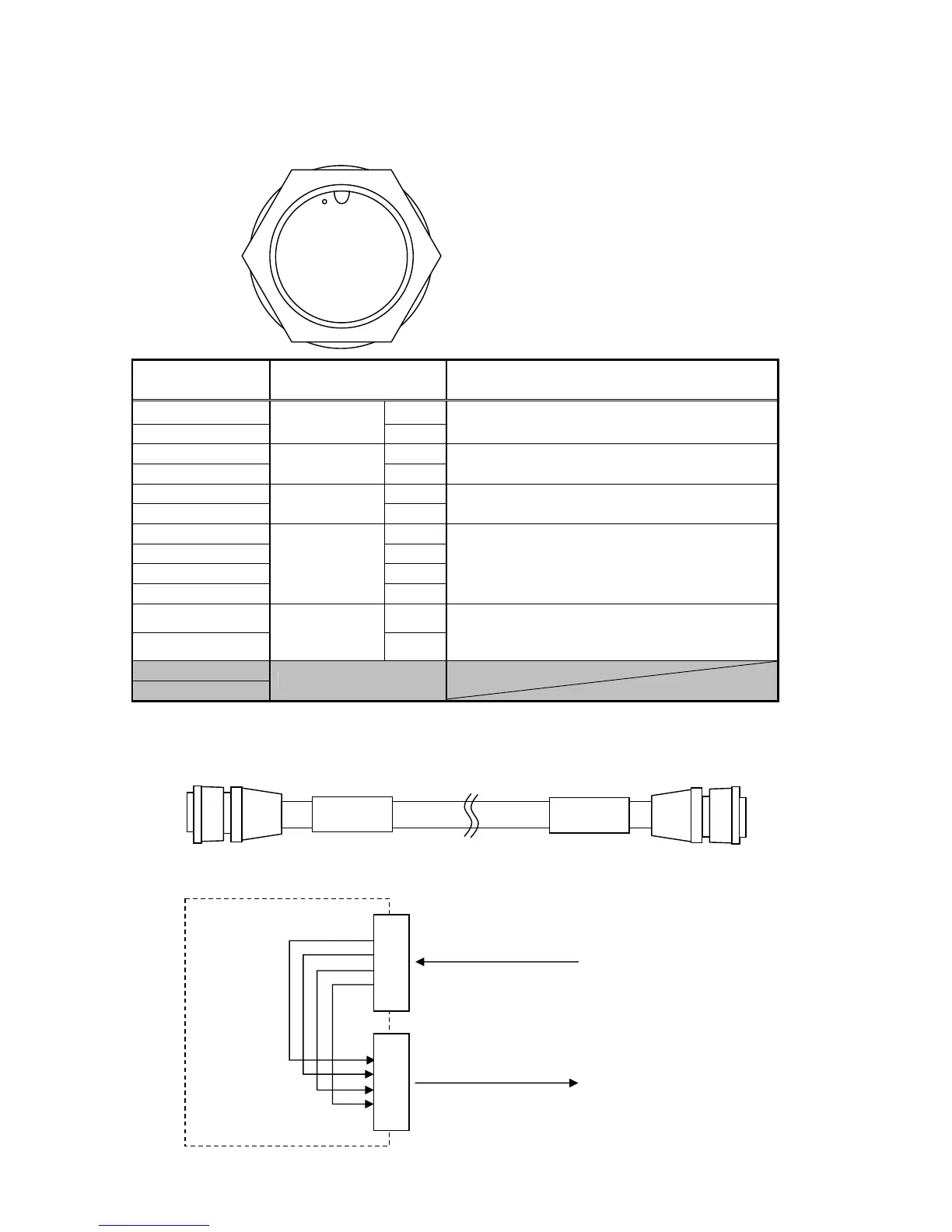
[Sensor Connector]
SENSOR
Data Cable: CFQ-7248 (included))
Terminal Number
(CFQ-7248)
Name Explanation
1 (Red Thick) 13V
2 (Black Thick)
Sensor
Power Supply
GND
Power to the sensor is supplied by the display
unit.
3 (Orange) A
4 (Yellow)
RXD0
B
Receives data from the sensor.
5 (Green) A
6 (Blue)
TXD0
B
Sends configuration data to the sensor.
7 (Purple) SD-A
8 (Grey) SD-B
9 (White) SC-A
10 (Black Thin)
Sensor
Through
SC-B
Outputs data from the sensor through [DATA
IN/OUT 1].
11 (Brown) A
12 (Pink)
TXD4B (*1)
B
Sends configuration data to the beacon
receiver.
(Option cable required)
13 (Light Blue)
14 (Light Green)
Unused
*1 : Outputs parallel to the DATA IN/OUT 2 connector 9 and 10 pins.
Connection Cable Appearance
● Sensor Through Terminal: The signal line are routed in the display unit as shown below.
① ②
③ ④ ⑤
⑥ ⑦ ⑧ ⑨
⑩ ⑪ ⑫
⑬ ⑭
SENSOR
DATA
IN/OUT 1
SD-A
SD-B
SC-A
SC-B
・
7
8
9
10
・
・
3
4
5
6
・
CFQ-5374
CFQ-7248
External Device
NNN-20/30
Sensor Unit
NWZ-4700
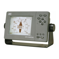
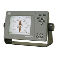
Display Unit
Interior
CFQ-7248
CFQ-7248
Cable Length: 10m