5-28
5.4.1 Antenna Check
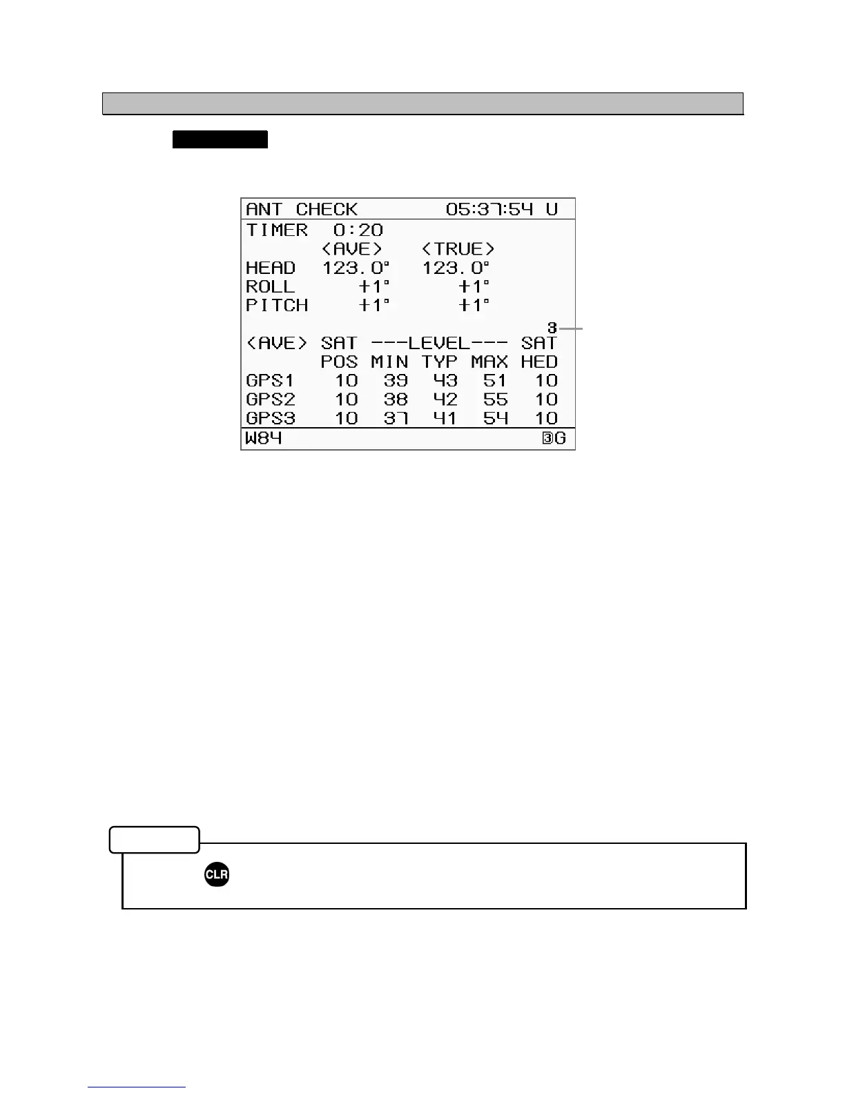
Selecting ANT CHECK from the "5.4 Maintenance Menu" displays information about the sensor.
This allows confirmation of the sensor status, and can be used to determine if the equipment is faulty.
The following items are displayed.
• TIMER: Time is counted from when this screen is displayed.
• HEAD: Average bow heading (AVE) and current measured heading value (TRUE) are
displayed.
Check that the displayed heading is correct.
• ROLL: Average roll (AVE) and measured roll value (TRUE) are displayed.
Confirm the indication matches to the ship’s rolling.
• PITCH: Average pitch (AVE) and measured pitch value (TRUE) are displayed.
Confirm the indication matches to the ship’s rolling.
• GPS1 - 3: Reception status of each GPS receiver is displayed.
SAT POS: Average number of satellites used for position measurement.
LEVEL: MIN (minimum), TYP (average), and MAX (maximum) signal levels
SAT HED: Average number of satellites used for bearing measurement.
Confirm the values of GPS1 thru GPS3 are almost the same. Also confirm the level
(TYP) is around 40 to 50.
• Antennas in use:
3 (If it is not “3”, the antenna installation position may not be suitable. Relocate the
sensor to the place with clear view.)
• Press to return to the Main Menu.
Antenna Check Screen
Memo
Antenna in use
3: With three antenna
2: With two antenna